A handful of good wire cutting images I identified:
Image from page 14 of “Merz’s practical cutting method for ladies’ jackets and cloaks ..” (1911)
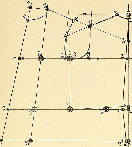
Image by Net Archive Book Images
Identifier: merzspracticalcu00merz
Title: Merz’s practical cutting program for ladies’ jackets and cloaks ..
Year: 1911 (1910s)
Authors: Merz, William. [from old catalog]
Subjects: Tailoring (Women’s) [from old catalog]
Publisher: [New York?] W. Merz
Contributing Library: The Library of Congress
Digitizing Sponsor: Sloan Foundation
View Book Web page: Book Viewer
About This Book: Catalog Entry
View All Photos: All Pictures From Book
Click right here to view book online to see this illustration in context in a browseable online version of this book.
Text Appearing Just before Image:
e and ]/> inch from 14 to 9= i8j4inches for 36 complete bust. On the waist line fnjin center point 19 to 20 is yi waist =six^4 inches, and from 20 to 21 waist measure, i2/four inches.Draw the front part guide line from 18 by means of 21 downwardsto establish 22, and from 21 by way of 18 upwards to establish2^. Front-depth measure is 113/^ inches. Take the backmeasure from five tO four = two inches, and with this amount continuedfrom 16 to 23, exactly where iiyi inches attain the line. Square outfrom 23 to 24 from 23 to 24 is i^ bust. Draw a straight linefrom 24 through 9, which establishes 10 and 11. From 24 to25 is % bust, and cur-e the collar line as represented. Point 26is % bust from 14, and draw the front shomlder line from 2t,to 26. To establish the back width, point 28, take half from14 and 17 and i^^ inches = 63/^ inches on this draft, from 14to 28. Draw the lines from 28 to 29 and from i(> to 2y parallelwith the back center line, 14 to five. l-roni point 16 to 27 is ,4 For Ladies Jackets and Cloaks. 13
Text Appearing Following Image:
Diagram I. bust less jS inch. Draw the back sh.mlder line from 27 to 4At point 29 the slioulder seam is enlarged 14 inch. For smallsleeves it ought to be enlarged ^ inch. Take the measure from4 to 29 and carry it over from 2:, to 30: then draw the arm-hole from 29 t(j 30, as represented. 14 Merzs Sensible Cutting Method Diagram II. The measures: Back depth six% Front waist length. . . 21^ Level waist lengili. . . i5–:4 Front depth 11^ Back waist length. . . . 153-4 Fwl bust 36 Height of bust 14 Full waist 25 The waist width necessary is from point 20 to 21. From20 to 12 is back waist surplus, and from 21 to ten is front waistsurplus. These are to be cut out as follows: Draw the line from 29 to 12, which establishes K. From12 to A is 34 back width. From A to B is ^/i,-, bust, ij/s inchesto be cut out. From B to C is % waist and 3^ inch. FromC to D is 3/two inch, for cutting out on all drafts. From D to Eis 34 inch far more than from B to C. From E to F is i3^ inches,which is the balance from t
Note About Images
Please note that these photos are extracted from scanned page photos that might have been digitally enhanced for readability – coloration and look of these illustrations might not completely resemble the original function.
Image from page 33 of “Valve setting: easy strategies of setting the plain slide valve. Meyer reduce-off. Corliss. and poppet types” (1908)
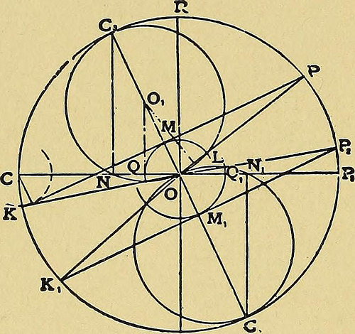
Image by World wide web Archive Book Pictures
Identifier: valvesettingsimp00coll
Title: Valve setting: basic strategies of setting the plain slide valve. Meyer cut-off. Corliss. and poppet varieties
Year: 1908 (1900s)
Authors: Collins, Hubert Edwin, 1872-
Subjects: Steam-engines
Publisher: New York [and so on.] Hill publishing organization
Contributing Library: The Library of Congress
Digitizing Sponsor: The Library of Congress
View Book Web page: Book Viewer
About This Book: Catalog Entry
View All Pictures: All Photos From Book
Click right here to view book on the internet to see this illustration in context in a browseable online version of this book.
Text Appearing Prior to Image:
r which the rest of the construction can readily becarried out. Dilemma IV. Provided the steam lap, steam lead, and the point ofcut-off. 22 VALVE SETTING In Fig. 20, let the angle C—0—P be that corresponding to the pointof reduce-off and draw in the lap circle Q M L, laying off at the very same timethe distance Q—N equal to the lead. Connect the points N and andthe points and L by straight lines, and erect a perpendicular to eachof these lines at its middle point. The point Oi at which these twoperpendiculars intersect will be the center of the steam-valve circle andthe radius will be the distance from it to the point , or either of thepoints N and L. The diameter of this circle is, of course, equal to onehalf the travel of the valve, so that the crank circle may readily beconstructed, and the angle Cg—0—R amongst the diameter of the valvecircle and the perpendicular erected from the point will be the angleof advance. It is, then, an straightforward matter to carry out the building and
Text Appearing Right after Image:
Note About Pictures
Please note that these images are extracted from scanned page photos that might have been digitally enhanced for readability – coloration and look of these illustrations could not perfectly resemble the original perform.