Klarm Machining Promotes CNC Milling Machining

Custom Fixtures

At the point when a section has an exceptional shape and needs exact area alongside a profoundly secure clasping framework, a custom installation can be utilized. An installation is a specially fabricated workholding gadget explicitly intended to oblige a particular part. This technique can be extremely valuable for protecting parts with abnormal shapes and permits reliable referring to from basic dimensional surfaces.

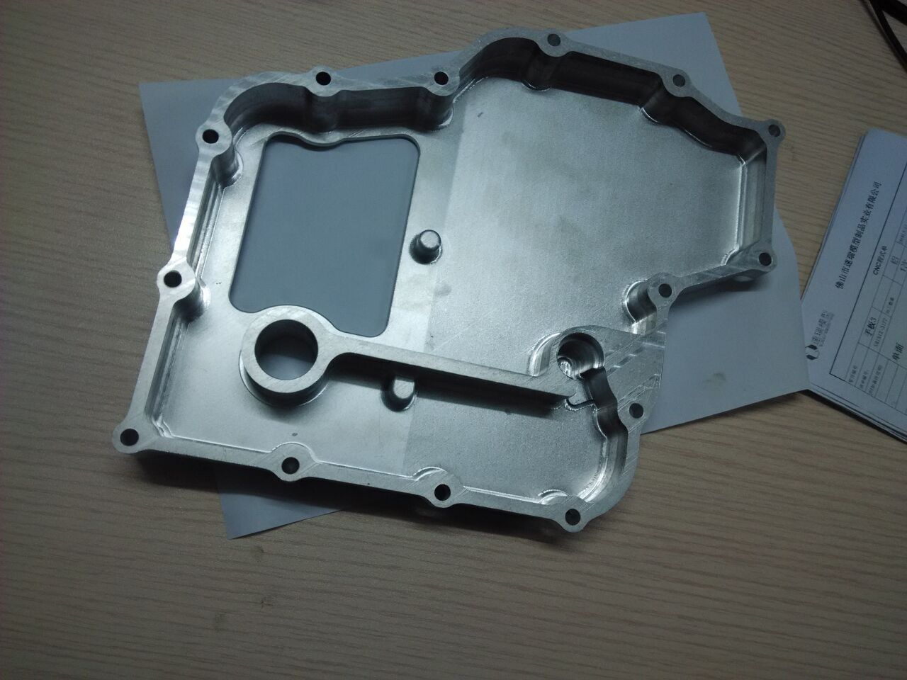
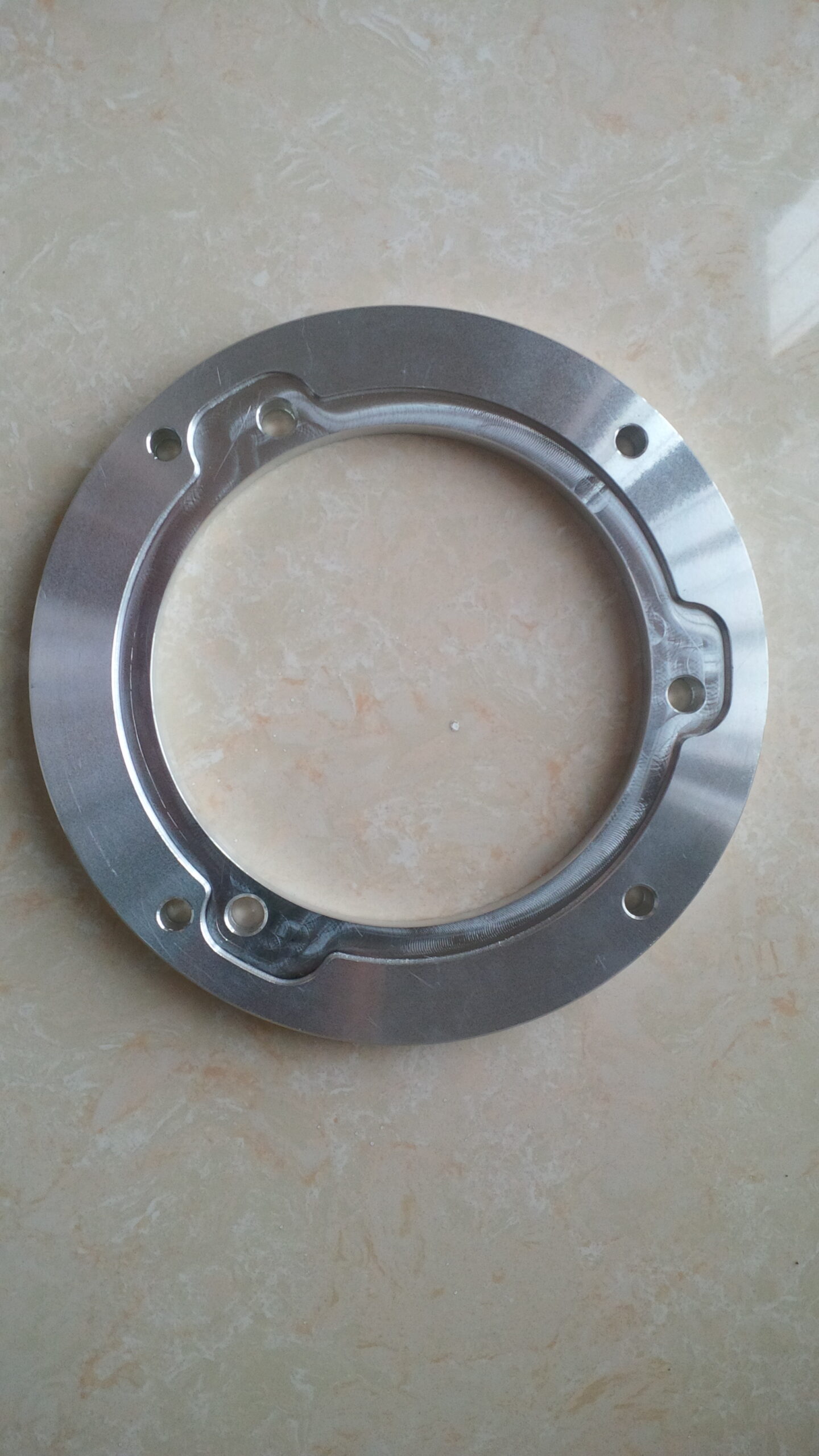
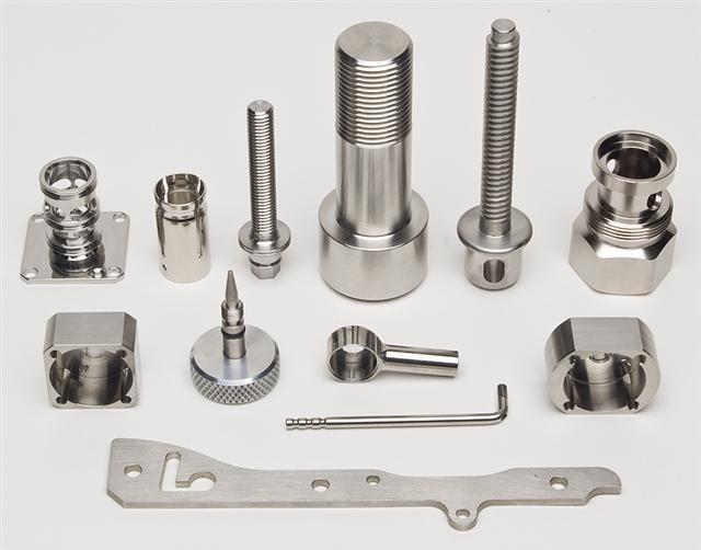
Installations are normally costly because of their absolutely custom nature, which requires a lot arranging, plan, custom machining, and numerous materials. Custom installations are generally braced straightforwardly to a machine table, bed, or gravestone. China precision machining services suppliers shows a custom apparatus.

Cycle PLANNING

Normal CNC processing activities incorporate face and fringe processing, opening, taking, two-dimensional shaping, three-dimensional surfacing, and holemaking. Every one of these individual undertakings is alluded to as an activity. The mix of all tasks needed to machine a section is known as an assembling interaction.

Before programming or setting up apparatuses and the machine, the designing drawing should be firmly analyzed and the creation of the part should be arranged beginning to end. The arranging of workholding gadgets, tooling, and the request for machining activities rely upon the part’s highlights, resiliences, and required surface completions determined by the drawing. When an intensive system has been resolved to deliver a section, the means are then definite on an archive called a cycle plan. This arrangement will incorporate a portrayal of every activity, the apparatuses required, speed and feed information, workholding data, different notes and remarks, and frequently a sketch portraying the part direction. This report is significant not just for the underlying programming of the part, yet additionally as a kind of perspective for any arrangement individual or administrator who will machine the part later on.

There is no normalized design for composing a CNC program that is viable with all machine control brands and models. Each machine control producer has built up its own interesting programming design.

Every one has minor contrasts, yet the standards of a program are something very similar among them all. The programming models all through this unit will relate the most near Fanuc-type and Haas regulators. Be that as it may, the standards might be applied to any producer’s organization (see each machine’s modifying manual).

Recollect from the CNC presentation unit that G90 sets supreme situating and G20 sets inch units. Presently the G17 has been added to set the XY plane, or the standard arrange framework direction. All programming models in this unit will be in outright mode and on the XY plane.

This article is from http://www.tinymachining.com

Klarm Machining Offers precision machining services china

CNC shell-plant and face-factory holders are basic arbors utilized for mounting shell factories and face factories. The arbor comprises of a round pilot distance across for precisely finding the focal point of the mounted instrument and two contradicting drive keys to forestall rotational slippage on the arbor. Cutters slip over the pilot and the drive keys with no power and the instrument is caught and attached by a fastener or cap screw. CNC machining products manufacturers china shows a face-plant toolholder for use in a CNC machining focus.

CNC Tapping Toolholders

There are a few varieties of CNC toolholders utilized for mounting taps. Some hold taps unbendingly in the holder. Others hold taps in particular spring-stacked gadgets that permit expansion and pressure. These are regularly called coasting holders. The machine’s ability for tapping figures out which kind of holder ought to be utilized by cnc precision machining company.

Taps can be held unbendingly with collet throws utilizing ER tap collets fabricated with an inward square that keeps the tap from turning inside the collet. Another technique for tap holding utilizes a spring-stacked brisk change connector to hold the tap. The connector would then be able to be mounted in an uncommonly planned gliding or inflexible tapping throw.

Workholding

CNC hardware and tooling are incredibly costly speculations, so it is reasonable that the additional time a machine spends really machining the item, the more productive the venture is. Workholding gadgets and strategies for machining focuses are consistently advancing and improving so that less time is invested stacking workpieces and more energy is spent machining.

Workholding gadgets for processing can go from basic clips and machine tight clamps to detailed and costly bed frameworks, headstones, and custom apparatuses.

Clips

Clips are a general strategy for connecting workpieces to a machine’s table. Similar styles utilized for manual processing can be utilized for CNC processing also. One kind of clasping framework is the progression block style that permits a stud or jolt to be moored to the machine table T-space and a lash to be drawn down onto a section’s surface to tie down it to the table. Toe cinches permit a section to be hung on its edges by utilizing exceptional serrated jaws to hold into the material and pull the work down close against the table.

Another variety is switch type cinches, which have a helpful snappy delivery switch that utilizes a cam activity component to give clipping pressure. China precision tooling manufacturer shows instances of these clip types.

Clasps are ideal for holding very huge or strangely molded workpieces, or creation work where a tight clamp isn’t reasonable and the volume of work doesn’t legitimize the cost of specially assembled apparatuses. Shockingly, holding work with braces gives no precise strategy to continued situating from one section to another. Each recently stacked workpiece may should be adjusted utilizing a dial pointer, at that point a reference area set utilizing an edge locater. Braces additionally require uncommon programming and administrator consideration since they as a rule reach out over the highest point of the workpiece surface, making the potential for crashes high. Figure 8.5.21 shows an enormous workpiece got to the table of a machining focus with step clasps.

This article is from http://www.tinymachining.com

Turning Tool Usage in CNC Machining

X apparatus balance is being set by igniting of an OD of 1.500″ with a 0.010″- thick sensor gage. The nonexistent diametral position the instrument is at is the workpiece width in addition to twice the sensor gage: 1.500 + 0.010 + 0.010 = 1.520. In the event that an ID exhausting, stringing, or cutting instrument is to be set, an unbending shim is utilized as a sensor to discover the OD surface of the workpiece as appeared (the shim isn’t utilized in the figuring).

When cnc turning manufacturer setting a turning device for the X-hub, the instrument tip is brought to the work width and ignited the OD of the part utilizing a piece of shim material or a sensor gage. At the point when an OD apparatus is ignited with a sensor gage against an external breadth, the device tip is at a fanciful width of the OD in addition to multiple times the antenna gage thickness. For instance, if the apparatus is ignited of an OD of 1.500″ with a 0.010″- thick antenna gage, the nonexistent measurement the device is at is the workpiece breadth in addition to twice the sensor gage: 1.500 + 0.010 + 0.010= 1.520. Numerous controls permit this number to be gone into the math counterbalance page and will ascertain the instrument balance sum consequently.

When china cnc turning and milling suppliers setting a math balance for an opening working device, the device might be adjusted on focus most precisely by “clearing” around the perimeter of the device with a pointer mounted in the machine shaft.

A cnc turning precision titanium parts factory shows a picture of an opening working device being cleared with an axle mounted pointer. When the opening working device is in arrangement, the device is at X-zero and there isn’t anything extra to make up for. The position is entered as the X calculation balance esteem. The Z-pivot counterbalance for opening working devices is set and changed a similar path likewise with turning and exhausting instruments.

The underlying settings of the device counterbalances are put away in the calculation balance page. Figure 8.4.19 shows a picture of an ordinary math balance page on the machine show screen. These numbers mirror the genuine setting for the device tip area in its unique and unworn state.

After the instrument has been set, a section is typically delivered by running the program interestingly. The part is then quickly reviewed and changes are made to the calculation balances on a case by case basis to accomplish wanted sizes. Here is a theoretical illustration of how these changes might be made for a turning apparatus (OD working):

  1. The initial segment is created and assessed.
  2. The estimation uncovers that every width (which is made by the X-pivot) for a given apparatus estimates 0.0008″ bigger than wanted size.
  3. The math balance page is opened and the current X-hub calculation balance for the device is 8.7899″.
  4. Then, 0.0008″ is deducted from the complete X-hub apparatus counterbalance an incentive for that instrument and it is resolved that 8.7891″ is the right calculation balance.
  5. The new worth is entered for that counterbalance.
  6. The following part is made and the revision is checked.

CNC Precision Machining Company Setting a Work

The workpiece arrangement technique builds up a work counterbalance or beginning area for the WCS. AIll workpiece arranges for programming will be referred to from this beginning. This is set up by finding the work counterbalance or “move” from the MCS starting point to the proposed WCS birthplace.

Review that the MCS never changes position. It is referred to at a similar position each time the machine is homed. Consider this point a perpetual reference point. Since the situation of this machine starting point never shows signs of change, yet the work cause changes with each new workpiece arrangement, the work balance for the part is characterized as a distance referred to from the MCS root. A few controls consider this counterbalance a workshift in light of the fact that it basically moves the machine inception to the area of the work beginning (or the other way around relying upon the machine). Carbon fiber cnc service factory shows an illustration portraying work counterbalance.

On turning machines, the workpiece will change long and position from one occupation to another and requires the cause to be reset in the Z-pivot for each new position. Notwithstanding, the middle line of the workpiece and the middle line of the axle hub are constantly adjusted, so the cause for the X-pivot stays as before from one occupation to another.

There are numerous varieties in the manner every maker’s machine is set up. The standards in the models portrayed next ought to apply to all machine controls.

Fundamental strides for setting a work balance:

  • The workpiece is introduced in the machine.
  • The turret is ordered to a confronting apparatus by utilizing the device change order.
  • The Z-hub is run to bring the confronting instrument close to the furthest limit of the workpiece.
  • The axle is begun utilizing the legitimate M3 or M4 code in MDI mode.
  • The part is looked by running a confronting device across the work utilizing the handwheel until the face is tidied up (no surface left un-machined).
  • The turret is run to a protected position and filed to a vacant position.
  • A gage block is held against the essence of the part.
  • The face of the turret is gradually and painstakingly ran against the gage block until a slight drag is felt. The length of the square is the separation from the planned part beginning to the essence of the turret (the reference point).
  • This gage block length is deducted from the current MCS Z-pivot position.
  • The coming about esteem addresses the separation from the MCS beginning to the WCS source for the Z-hub and is gone into the work balance page in the MCU.

The china cnc machining process supplier shows an illustration portraying the part, gage square, and turret being utilized to set a work balance.

It is a common misinterpretation that the drawtube string commitment affects cinching pressure. The drawtube just sets the size range among open and shut position. Eventually, the grasping pressing factor is resolved exclusively by the machine’s air or pressure driven controller for the collet/hurl nearer framework.

Some turning MCUs such as precision stainless steel cnc turned parts manufacturers utilize a less complex technique, and as opposed to deciding a genuine distance, they simply require a “set Z” catch to be squeezed. The MCU consequently plays out the computation and stores the right an incentive on the work counterbalance page.

Set Up the Workingholding in CNC Machining

When the workholding gadget is picked, it is mounted by the maker’s rules. When utilizing a hurl, machinable delicate jaws are frequently utilized in china professional cnc machining center. Delicate jaws can be redone to oblige the state of the workpiece. Frequently, the jaws are exhausted while introduced on the hurl to build up the right grasping sweep where the jaw contacts the part. It is a decent practice to exhaust the jaws while they are preloaded by clipping on a piece of scrap or a hurling ring.

This mimics the anxieties the toss will be under when the real workpiece is held. The bracing strain to be utilized for grasping the work ought to likewise be set a similar when exhausting the jaws. A carbon fibre cnc cutting factory shows an image of suitably exhausted delicate toss jaws and a mating workpiece.

In the case of utilizing a collet, place the collet closer catch in the vacant position. The collet should be lined up with its key and embedded into a perfect shaft nose tighten. String the drawtube onto the collet from the opposite finish of the headstock. Spot a workpiece of the right breadth into the collet and hand-fix the drawtube until the part is held cozily. Release the drawtube a half-transform prior to securing it set up to set up the appropriate leeway for stacking and dumping workpieces. In the event that the draw tube is left cozy with the collet closer in the”open” position, workpieces won’t handily slide all through the collet during part changes (the collet can’t deliver enough).

Regardless of whether a collet or a throw is utilized, the suitable clasping pressure should be set. A lot grasping pressing factor can misshape the workpiece and too small clipping pressing factor can permit the work to slip or be pulled out of the collet or throw during machining. Too little pressing factor will likewise permit the holding power to be overwhelmed by radial power at high RPM. The china CNC machining parts manufacturers show the impacts of holding pressure versus RPM on one producer’s machines. The pressing factor of the collet/toss nearer framework is controlled either by a pneumatic or water powered controller, contingent upon the machine. The holding pressure is changed with this controller. (Allude to the machine manual for explicit strategy.)

When the workholding gadget has been set, the workpiece to be utilized for arrangement may now be held. It is critical to permit sufficient workpiece length to stretch out of the toss or collet so that there is no impact with the throw jaws or the collet face during any of the modified machining activities. Ordinarily, 1/8 ” of least leeway ought to be kept up between the cutting instrument and the workholding gadget.

It is a typical misconception for high precision machining parts factory that the draw tube string commitment affects bracing pressing factor. The draw tube just sets the size range among open and shut position. Eventually, the grasping pressing factor is resolved simply by the machine’s air or water driven controller for the collet/toss nearer framework.

This article is from http://www.tinymachining.com/