Turning Tool Usage in CNC Machining

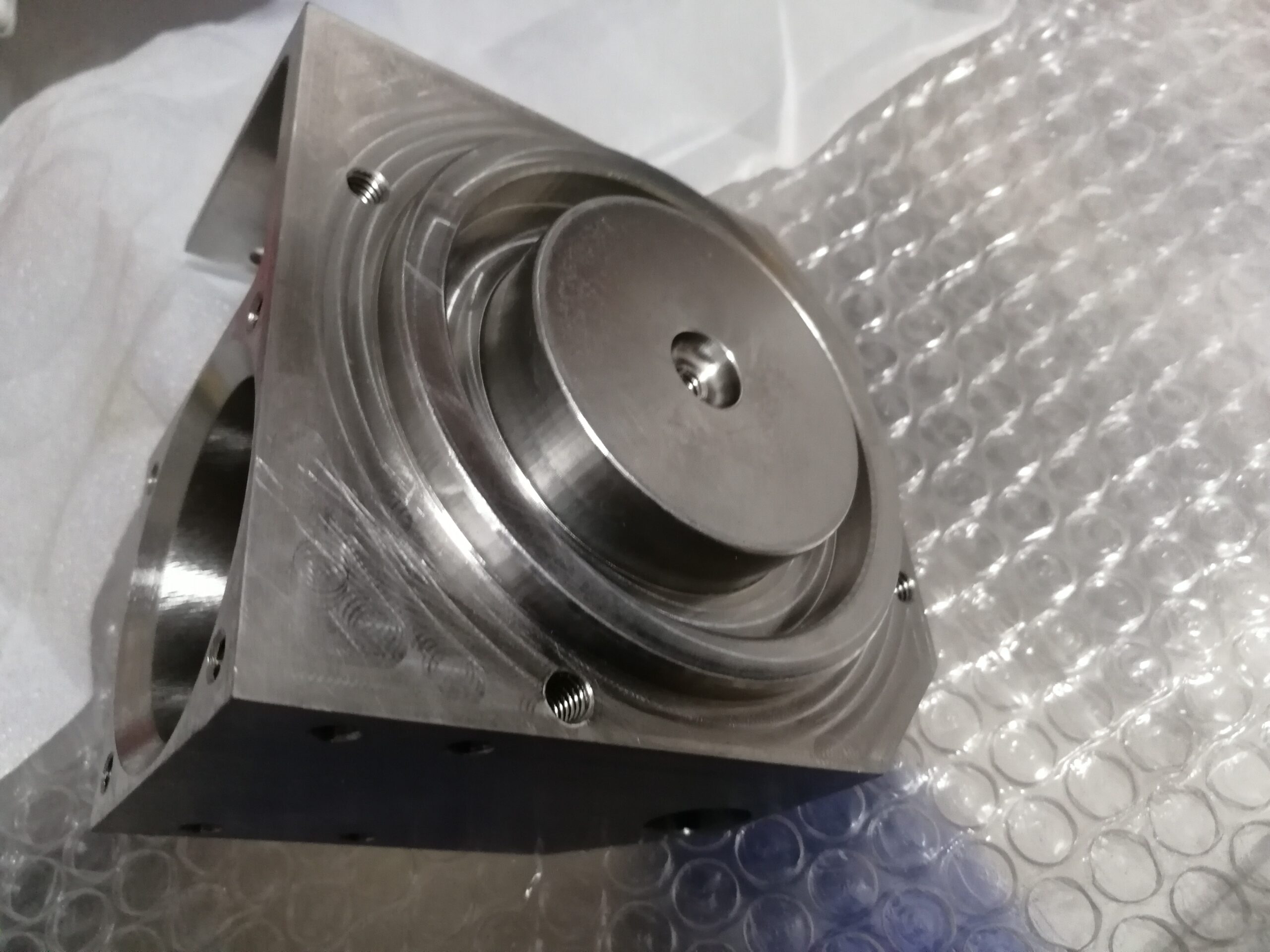
X apparatus balance is being set by igniting of an OD of 1.500″ with a 0.010″- thick sensor gage. The nonexistent diametral position the instrument is at is the workpiece width in addition to twice the sensor gage: 1.500 + 0.010 + 0.010 = 1.520. In the event that an ID exhausting, stringing, or cutting instrument is to be set, an unbending shim is utilized as a sensor to discover the OD surface of the workpiece as appeared (the shim isn’t utilized in the figuring).

When cnc turning manufacturer setting a turning device for the X-hub, the instrument tip is brought to the work width and ignited the OD of the part utilizing a piece of shim material or a sensor gage. At the point when an OD apparatus is ignited with a sensor gage against an external breadth, the device tip is at a fanciful width of the OD in addition to multiple times the antenna gage thickness. For instance, if the apparatus is ignited of an OD of 1.500″ with a 0.010″- thick antenna gage, the nonexistent measurement the device is at is the workpiece breadth in addition to twice the sensor gage: 1.500 + 0.010 + 0.010= 1.520. Numerous controls permit this number to be gone into the math counterbalance page and will ascertain the instrument balance sum consequently.

When china cnc turning and milling suppliers setting a math balance for an opening working device, the device might be adjusted on focus most precisely by “clearing” around the perimeter of the device with a pointer mounted in the machine shaft.

A cnc turning precision titanium parts factory shows a picture of an opening working device being cleared with an axle mounted pointer. When the opening working device is in arrangement, the device is at X-zero and there isn’t anything extra to make up for. The position is entered as the X calculation balance esteem. The Z-pivot counterbalance for opening working devices is set and changed a similar path likewise with turning and exhausting instruments.

The underlying settings of the device counterbalances are put away in the calculation balance page. Figure 8.4.19 shows a picture of an ordinary math balance page on the machine show screen. These numbers mirror the genuine setting for the device tip area in its unique and unworn state.

After the instrument has been set, a section is typically delivered by running the program interestingly. The part is then quickly reviewed and changes are made to the calculation balances on a case by case basis to accomplish wanted sizes. Here is a theoretical illustration of how these changes might be made for a turning apparatus (OD working):

  1. The initial segment is created and assessed.
  2. The estimation uncovers that every width (which is made by the X-pivot) for a given apparatus estimates 0.0008″ bigger than wanted size.
  3. The math balance page is opened and the current X-hub calculation balance for the device is 8.7899″.
  4. Then, 0.0008″ is deducted from the complete X-hub apparatus counterbalance an incentive for that instrument and it is resolved that 8.7891″ is the right calculation balance.
  5. The new worth is entered for that counterbalance.
  6. The following part is made and the revision is checked.

Drilling and Beaming

Drilling on the machine is like boring on a drill press aside from that the work turns rather than the drill.

Straight-shank drills are held in drill tosses mounted in the tailstock, while tighten shank drills can be mounted straightforwardly in the tailstock. Drill sleeves and attachments can be utilized to adjust diverse shape sizes to fit the tailstock tighten. When boring openings bigger than 1/2″ in width, drilling with a pilot drill first will enormously decrease the feed compel needed to bore the bigger size. Utilize a pilot drill measurement that is marginally bigger than the width of the right on target of the bigger drill.

Follow these means for boring on the machine.

  • Calculate and set a suitable shaft speed. While figuring axle speed, utilize the measurement of the drill.
  • Mount the drill in the tailstock.
  • Position the tailstock with the drill close to the essence of the workpiece and lock the tailstock to the ways.
  • Start the shaft.
  • Apply a proper slicing liquid to the tip and in the flutes of the drill. The slicing liquid applied to the bleeding edges greases up and cools the cutting zone. The liquid in the flutes enables the chips to slide through the flutes and out of the opening.
  • Since not many machines have power feed on the tail-stock, advance the drill with the plume feed hand wheel. At the point when full breadth is reached, note the graduations on the tailstock plume or hand wheel. The opening profundity will be referred to from this position. (Some hand wheels have a collar that can be set to “0”.)
  • Drill utilizing the tailstock hand wheel to propel the drill. In the event that the drill creates a shrill screeching sound and additionally fine wiry chips, the feed rate ought to be expanded. On the off chance that the chips are purple or blue and the shaft is working, the feed ought to be diminished.
  • Frequently withdraw the drill to get chips out of the opening and to continue cutting liquid on the drill.
  • Use graduations on the plume and the hand wheel to control profundity. china high quality machining parts shows a boring procedure on the machine. Ill-advised speed or takes care of as well as insufficient cutting liquid can cause the drill tip to turn out to be exceptionally hot and “weld” itself to the workpiece. This can prompt drill breakage and flying trash that can cause injury.
  • cof

Reaming

Reaming is performed on the machine to marginally broaden a penetrated opening to a size more precise than a drill can create and to deliver a smooth surface completion. The size of the opening that ought to be penetrated prior to reaming relies upon the ideal completed opening size. Utilize these rules for drilling or get ready for reaming precision machined components china:

  • Drill about 0.010″ underestimate for reaming openings 1/4″ measurement and under.
  • Drill about 0.015″ underestimate for reaming openings between 1/4″ and 1/2″ measurement.
  • Drill about 0.020″ underestimate for reaming openings between 1/2″ and 1″ measurement.
  • Drill about 0.030″ underestimate for reaming openings more than 1″ in measurement. Reamers may likewise have straight or Morse tighten shanks like wind penetrates and are mounted by similar strategies utilized by stainless steel precision milling part manufacturers china for mounting drills.
  • Mount the reamer in the tailstock and position the reamer close to the opening.
  • Lock the tailstock to the ways.
  • Set a shaft speed around one-a large portion of the speed as would be utilized for a drill of a similar size.
  • Apply sufficient slicing liquid to the reamer.
  • Advance the reamer until it just contacts the opening.
  • Note the graduations on the tailstock plume or hand wheel. (Some hand wheels have a collar that can be set to “0”.)
  • Feed the reamer into the work at about double the rate utilized for a comparative estimated boring tool. It is critical to keep a reamer moving at this steady rate so that each forefront is entering the material and a reliable surface completion is accomplished.
  • As with drilling, utilize the plume and hand wheel graduations to screen profundity. china brass cnc machining parts suppliers shows a reaming activity being performed on the machine.

Counterboring and Countersinking

Counterboring and subsetting tasks can be performed on the machine with the tailstock utilizing similar strategies utilized for drilling and reaming.

This article is from http://www.tinymachining.com

Tap Styles

NPT is the truncation for National Pipe Thread. These threads are tightened 3/4 inch for every foot to help seal them as they fix together. NPT threads are estimated by the ostensible inside line width instead of the significant thread measurement. Most tap drill diagrams additionally list pipe thread tap drill sizes.

Taps are accessible in numerous styles and chamfer types for different necessities in precision machined components china. These two qualities make drastically various outcomes when utilizing a tap.

The tap style profoundly affects the manner in which the chips are framed when the tap is being used. The most well-known are the following:

  • Hand Tap-Hand taps cut threads and have straight woodwinds from the tip toward the shank. These taps twist the chips firmly and break them into little pieces. The chips are generally put away in the flutes while the tap is being used.
  • Spiral-Point (Gun) Tap- – These taps likewise cut threads and have straight woodwinds with an uncommon edge ground on their finishes. The point on the end serves to make wiry chips that are extended forward as the tap is being used by cnc machining components suppliers. Since the chips are pushed forward, these taps are typically utilized on through gaps where the chips can escape out the base of the opening.
  • Spiral-Flute Tap- – These taps likewise cut threads and have a winding woodwind much like the flutes on a curve drill. Like a bend drill, these winding scores move the chips in reverse out of the gap while the tap is being used.
  • Thread Forming Tap- – These taps don’t cut, however structure threads by dislodging material into the state of the threads. They are frequently utilized with malleable materials, for example, aluminum. No chips are delivered by a thread framing tap.

At the point when taps are made by china precision machining manufacturers, short chamfers are ground onto their closures. This outcomes in each driving thread being dynamically bigger than the thread before it. This treatment makes the tap simpler to begin in the penetrated gap. There are three fundamental chamfer types accessible and they can be bought as a set. They are as per the following:

  • Taper Chamfer Tap- – These taps are now and then called starter taps, since they might be utilized to begin a tapped gap that will be done with another tap.

The threads on these taps have 7 to 10 threads chamfered to make the tap simpler to begin the opening. Tighten taps are generally utilized for tapping through openings. It is a typical misstep to imagine that these taps produce tightened threads like those utilized for pipe fittings.

Notwithstanding, these taps are just chamfered on the finish of the tap to make beginning simpler. These taps DO deliver straight threads.

  • Plug Chamfer Taps- – These taps are the most broadly useful of the three and they are either utilized without anyone else or after a shape tap when it is important to thread further into an opening. Attachment taps have three to five threads chamfered. These taps might be utilized in through gaps or in daze gaps (when an opening doesn’t go completely through a workpiece) when there is satisfactory clear-ance in the base of the opening.
  • Bottoming Chamfer Taps- – These taps are utilized when an opening is visually impaired, since they can cut full threads practically right to the base of a gap. These taps just chamfer the first or two threads.
  • This article is from http://www.tinymachining.com.