Surface Machining

The principal surface of a workpiece is regularly just ground until the ideal surface completion is reached. After the ideal measure of material is eliminated, turn off the coolant stream first, at that point the axle. This assists with eliminating coolant from the wheel before it halts. Try not to stream coolant over a fixed wheel on the grounds that the coolant can splash into certain sorts of haggles them to get uneven. At the point when restarted, an immersed wheel may create runout and produce a helpless surface completion.

After the main side of the workpiece is done, eliminate it from the machine, and flip it over to crush the contrary side utilizing similar advances.

Crushing the Magnetic Chuck

Over the long haul, the outside of the attractive throw can get worn or mutilated. In the event that the toss surface is not, at this point level, delivering equal or level surfaces can be almost incomprehensible. Pounding the genuine throw surface can make it level once more. Utilize similar procedures as when granulating any surface. Since the toss surface is typically huge, warmth can develop rapidly, so take cut profundities of just 0.0001″ to 0.0003″, utilize coolant when accessible, and flash out to be certain the surface remaining parts level.

Pounding PERPENDICULAR SURFACES

A couple of various techniques can be utilized to crush opposite surfaces. For the most part, the surface to be ground is situated corresponding to the attractive throw. When situated, the surface is ground utilizing a similar strategy utilized for granulating equal surfaces.

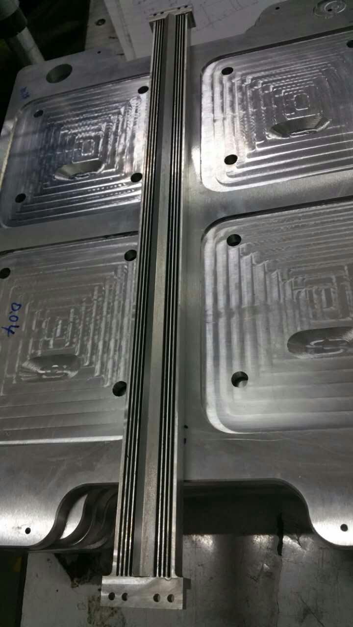
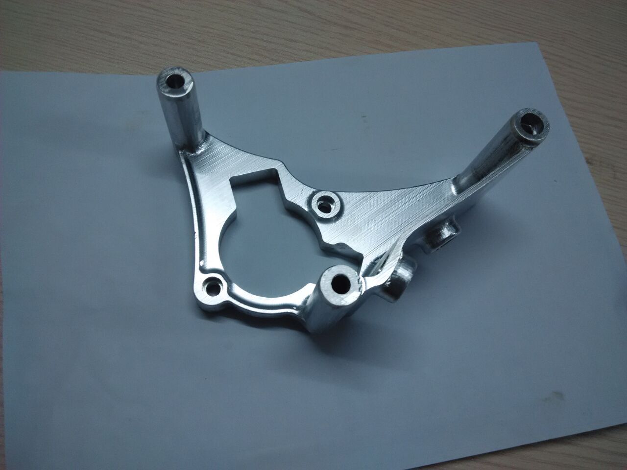
One technique for holding the work is for big cnc machined part made in china to utilize a point plate. The point plate can be mounted straightforwardly on the attractive toss and the part cinched with one of the initial two ground sides against its vertical surface. On the off chance that utilizing an attractive point plate, clips are not required however check for sufficient holding power much the same as when cnc precision machining factory utilizing the attractive throw. This cycle is like the processing cycle of putting the principal processed side against a strong tight clamp jaw or point plate. An equal can be utilized to raise the work over the top surface of the point plate. On the off chance that a nearby surface likewise should be ground, expand that surface past one finish of the point plate so it very well may be ground when the point plate is repositioned.

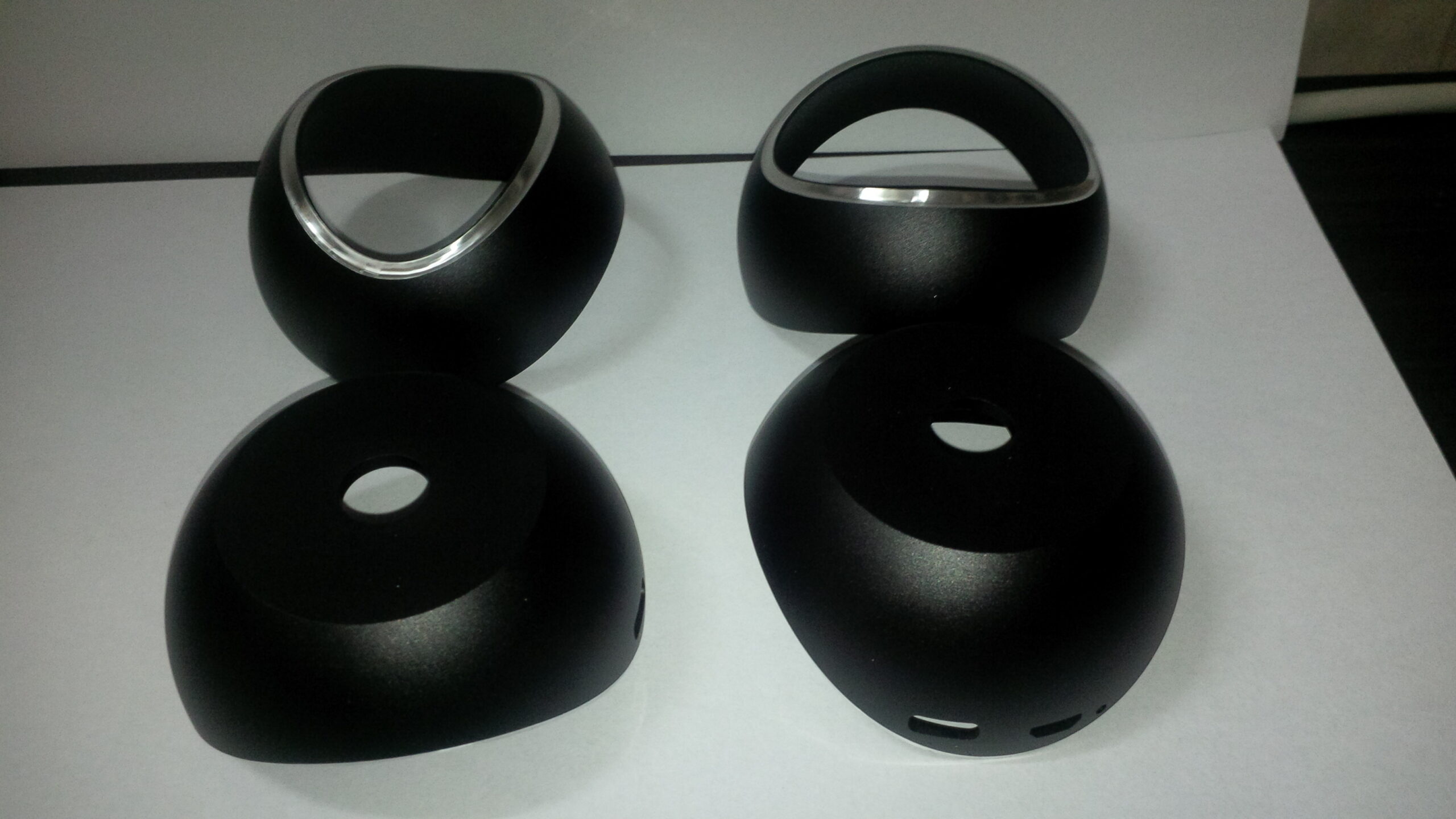
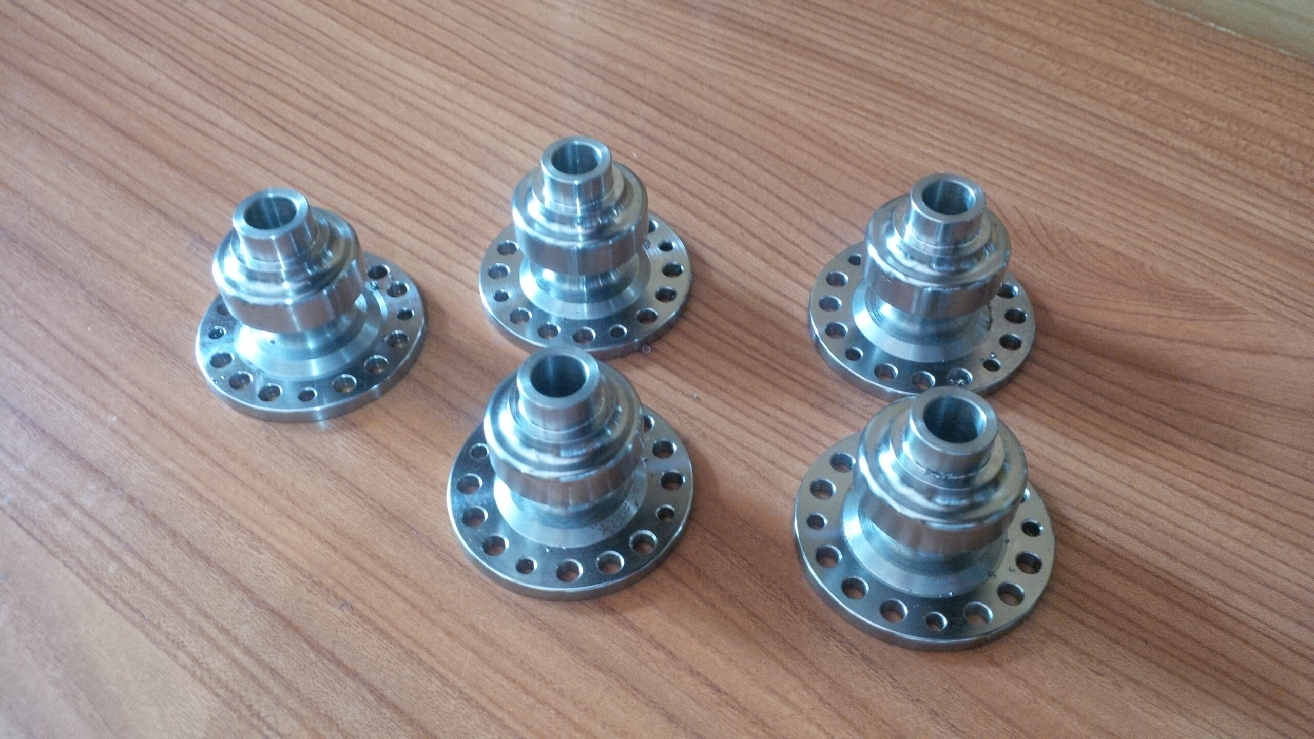
Granulate the surface that is corresponding to the attractive hurl first. At that point reposition clips, while keeping at least two braces on the part consistently. This keeps the workpiece from evolving position, with the goal that the point plate can be turned on its side to granulate the contiguous surface of the workpiece, as appeared in custom cnc machined precision machining titanium parts factory. Continuously use in any event two braces on the work while crushing so the part stays secure on the point plate.

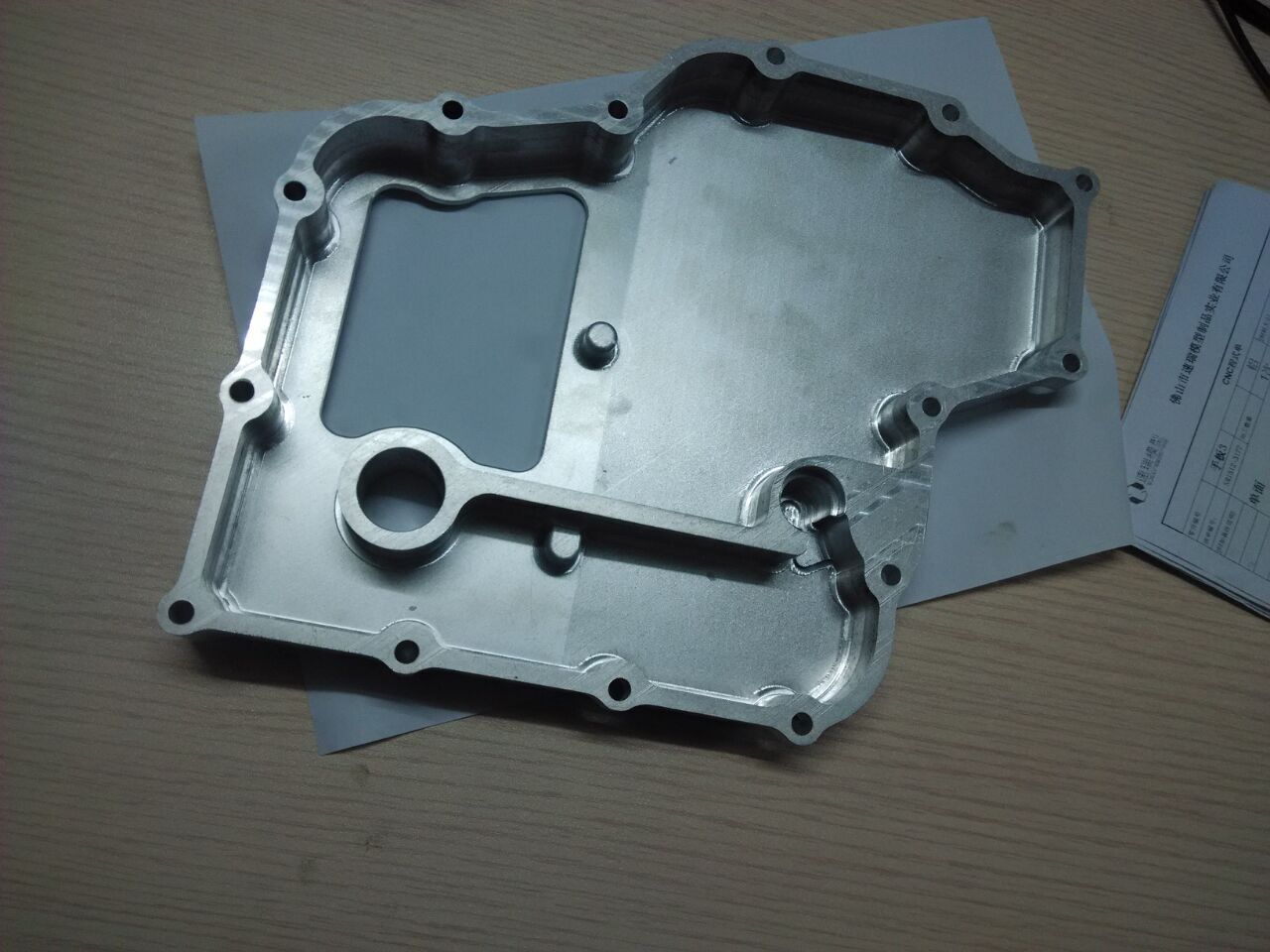
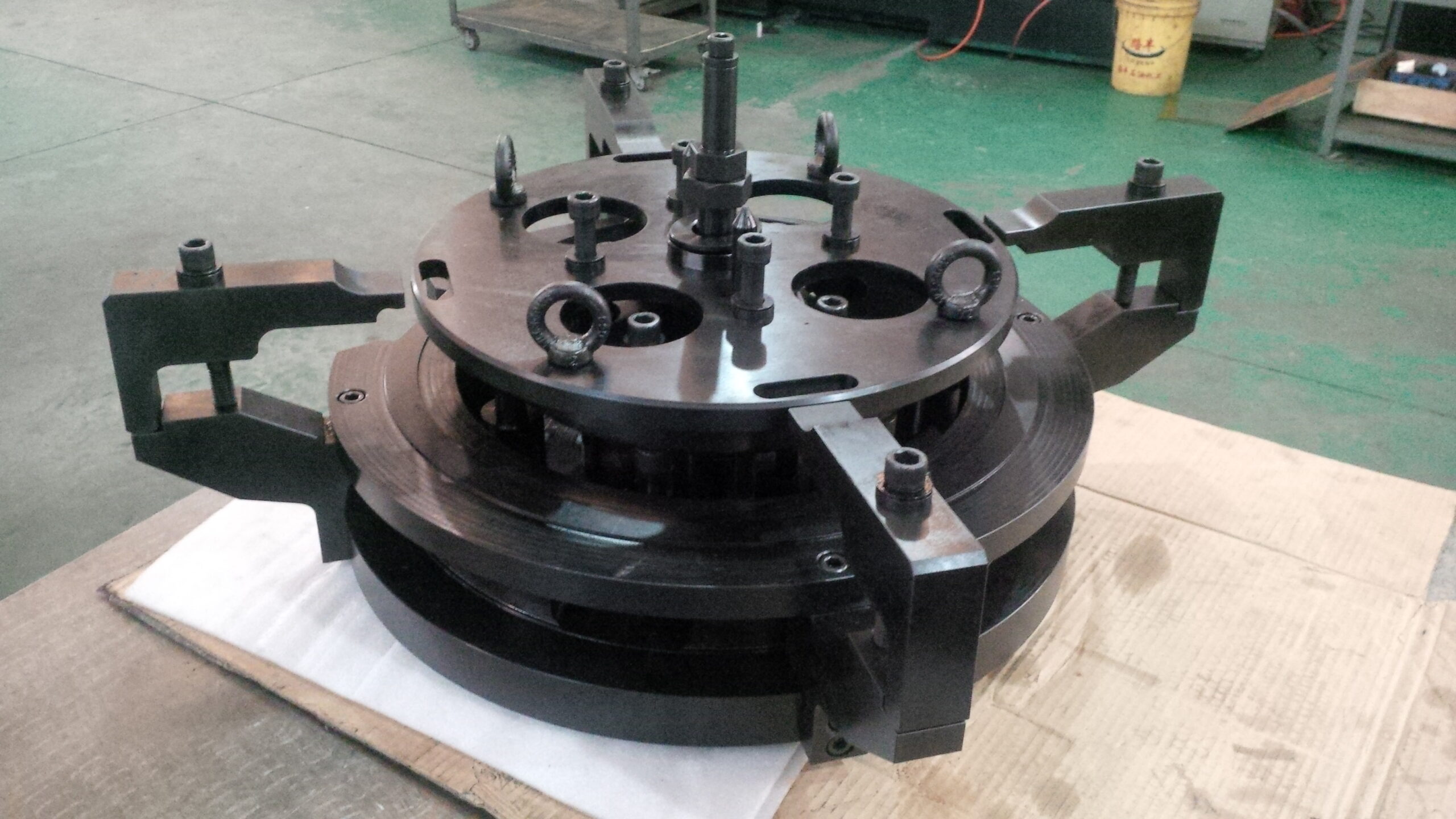
A comparative strategy utilizes a crushing tight clamp rather than a point plate. The tight clamp can be mounted straightforwardly on the attractive throw. At that point secure the workpiece in the tight clamp with one surface over the highest point of the tight clamp jaws and one end reaching out past one finish of the tight clamp, as appeared in china precision tooling manufacturers. Subsequent to granulating the top surface, the whole pounding tight clamp can be set on its side to crush the end opposite to different sides.

Utilizing either technique, now the work ought to have two equal sides, and two different sides that are opposite to those surfaces. The leftover surfaces would then be able to be ground corresponding to the recently completed sides. This article is from http://www.tinymachining.com/

Magnetic Chuck

In the event that a workpiece is taller than its length or width, the attractive hurl may not be sufficiently able to hold the part. Impeding can be utilized to help secure the part to the throw and keep it from tipping or being pulled from the toss. Squares are put firmly around the workpiece prior to enacting the magnet. Since the best power while granulating is toward the longitudinal table feed, hindering on the left and right sides of the workpiece is generally basic. This strategy can likewise be utilized to make sure about workpieces that are not ferromagnetic. China precision machining parts suppliers shows a technique for hindering work on an attractive toss. Slight workpieces that are not ferromagnetic can likewise be hung on the attractive hurl utilizing adaptable clasps. These utilization the attractive power of the hurl to pull little fingers against inverse edges of the part, holding it set up during pounding.

In the event that a workpiece contains highlights that shield it from being put level on the attractive throw, attractive equals may at times be utilized to help the workpiece. Attractive equals are not attractive without help from anyone else but rather are intended to expand the attractive field of the toss to the workpiece. Precision cnc machining service factory shows a couple of attractive equals. An attractive V-square can be utilized to hold a workpiece at a 45-degree point. There are two kinds of attractive V-blocks. One sort is similar plan as attractive equals and expands the attraction of the toss to the workpiece. The other kind has a switch like a perpetual attractive toss. The workpiece is essentially positioned in the V-block and the switch go to initiate the magnet.

An attractive point plate can be utilized by precision micromachining factory to hold work vertically and for figuring out tasks a lot of like a standard point plate. It has a perpetual attractive control much the same as the attractive hurl to hold workpieces. It very well may be made sure about to the processor’s attractive throw similarly a workpiece would be.

Accuracy points can be ground utilizing an attractive sine hurl. The sine toss is set up much the same as a customary sine plate however has its own lasting magnet to hold the work. It is a mix of a sine plate and an attractive throw. The hurl parcel has a back and end rail like numerous standard attractive tosses to adjust workpieces on the throw surface. The whole unit would then be able to be made sure about to the processor’s attractive toss.

Workpieces can get charged subsequent to being held by attractive apparatuses. A demagnetizer can be utilized to eliminate attraction from the work. The demagnetizer is turned on and the workpiece got across its surface. A demagnetizer is appeared in china cnc machining process suppliers .

When utilizing any attractive workholding gadget, consistently make certain to initiate the magnet and twofold watch that the magnet is working by attempting to move the workpiece by hand.The gold-shaded territories on the throw are the nonferrous portions where the attractive fields are made. The workpiece should traverse at least 3 of these sections to be securely made sure about. Notice the back rail on this hurl. It is utilized to help adjust a workpiece on the hurl. This article is from http://www.tinymachining.com/

Wheels

The crushing wheel is the cutting apparatus utilized in accuracy granulating activities. These wheels are like the wheels utilized by precision machining services china for random granulating in light of the fact that they are made of grating grains held along with a holding specialist, or bond. The holding specialist goes about as the “stick” that holds the individual abrasives together looking like a wheel. There are a lot more varieties of wheels accessible for exactness pounding versus those utilized for random granulating. Understanding the various sorts and qualities of pounding wheels will help in choosing a legitimate wheel to play out the necessary crushing activity.

WHEEL SHAPES

Crushing wheels come in various shapes, as delineated in china high quality stainless steel cnc machining. The Type 1 straight wheel is likely the most broadly utilized wheel for surface and barrel shaped pounding tasks. Recessed and eased wheels are additionally at times utilized for surface and chamber pounding to limit contact between the sides of the haggle workpiece. Cup, saucer, and dish-molded wheels are normally utilized for device and shaper granulating tasks. Cup-molded wheels are likewise utilized on some vertical shaft surface processors. The essence of a pounding wheel is the surface that is intended to be : utilized for crushing. By and large the outskirts (outside width surface) is the essence of the wheel. Now and again the wheel face is the level surface of the wheel, as with cup wheels. Notwithstanding, under the correct conditions, other wheel surfaces can likewise be utilized. For instance, the outskirts and the side of a straight wheel could be utilized to at the same time granulate a level surface and a neighboring vertical surface on a surface processor. The fringe and side of a recessed wheel could be utilized to pound both an external measurement and a shoulder simultaneously utilizing an O.D. processor. cnc spcical machines manufacturers china shows a few instances of arbor-mounted wheel shapes that are utilized for inner width granulating tasks.

Smile DING-WH EEL SPECIFICATIONS

Past wheel shapes, there is a normalized framework for depicting particulars for most pounding wheels dependent on five attributes. These five attributes are rough sort, coarseness or grain size, evaluation, structure, and bond type. Markings on the blotting surface of a granulating wheel will distinguish these qualities as per the normalized framework. The discretionary prefix and the last a couple of digits are markings utilized by singular makers. The excess numbers and letters recognize the five wheel qualities. Precision cnc milling parts manufacturers sums up this framework. Allude to it while perusing every portrayal.

Grating Type

Most pounding wheels are produced using either aluminum oxide, a blend of aluminum oxide and artistic aluminum oxide, or silicon carbide. Aluminum oxide and earthenware aluminum oxide wheels are recognized by the letter A, and silicon carbide wheels by the letter C. Various assortments of every grating kind may likewise contain different letters. The various assortments have various degrees of friabilit. Friability is the capacity of the individual grating grains to break during pounding to make new, sharp bleeding edges. Wheels that are more friable produce less warmth when pounding and are by and large utilized when granulating more enthusiastically materials. Less friable wheels are harder, hold their shape better, and are for the most part utilized when granulating gentler materials.

This article is from http://www.tinymachining.com/

collet blocks

One basic activity is to process a square on a tube shaped workpiece utilizing a square collet block. Here is an illustration of how to process a/2″ square on a 3%4″ distance across workpiece.

  • First decide profundity of slice for the pads to be machined. Take away the ideal distance across the square from the earliest starting point measurement. So 34-V2 = V4 or 0.250. A big part of that sum should be machined from each side, so 0.125″ should be eliminated at four areas 90 degrees separated.
  • Mount the 3%”diameter workpiece in the square collet block.
  • Mount the square in a processing tight clamp. Since the square should be eliminated from the tight clamp, pivoted, and remounted in the tight clamp, utilizing a workstop is useful.
  • Mount a cutting apparatus in the shaft, at that point figure and set axle RPM.
  • Position the plume with the micrometer changing nut against the stop so the apparatus is around 1/16″ over the workpiece, and afterward lock the plume.
  • Position the apparatus for the ideal length of the level.
  • Start the shaft.
  • Raise the knee to ignite the instrument the highest point of the workpiece.
  • Clear the device from the workpiece and set cut profundity with the knee. It is a decent practice to leave about 0.010″ to 0.015″ to check size prior to wrapping up.
  • Mill the main level as appeared in china precision machining oem parts.
  • Stop the shaft.
  • Remove the square, pivot it 90 degrees, and remount it in the tight clamp against the workstop.
  • Mill the subsequent level as appeared in china high-precision tooling suppliers.
  • Repeat the cycle for the excess two pads.
  • Stop the shaft and measure the distance across the pads.
  • Adjust profundity with the knee varying to plant to the ideal size.
  • Remember that cut profundity will be one portion of the absolute size distinction. For instance, if the distance across the pads is 0.020″ over the ideal size, machine an extra 0.010″ from every level.

A hexagon can be machined utilizing a hexagon collet block by following similar advances.

An ordering apparatus has a shaft that can be turned physically and afterward secured wanted positions. Situating the workpiece in this kind of apparatus is called direct ordering. An ordering installation regularly utilizes a three-jaw throw or a collet to make sure about the workpiece. Most can be mounted on a level plane or vertically. custom cnc machined precision machining titanium parts suppliers shows a collet type ordering installation. The ordering installation has a ring with certain number of indents around its perimeter. Regular quantities of notchesare 18, 24, 30, and 36. A few models can change the ordering ring, while others don’t. The ordering ring is picked dependent on the number of divisions should be machined on the workpiece. These divisions are dictated by number of highlights to be machined.

This article is from http://www.tinymachining.com/

Rotational Table Setup

Revolving TABLE

The revolving table comprises of a substantial base on which a round worktable is mounted. Numerous rotating tables can be mounted either evenly or vertically. The table contains T-spaces for mounting work and is associated with the base by heading that permit it to be turned easily and precisely. The table has degree graduations around its outskirts to help in situating. A hand wheel associated with a stuff set is utilized to pivot the table. Since the stuff set produces gear decrease, the hand wheel should be pivoted a few times to make one upheaval of the table.

This stuff decrease builds precision and control when situating the table. The turning table might be secured position to keep it from floating during arrangement or machining. Numerous rotational tables have a middle opening right through the work table, and some have a Morse tighten inside this opening for mounting tighten shank work-holding gadgets. chinese mold component machining suppliers shows a turning table.

Rotational Table Setup

Most revolving table tasks include mounting the rotational table evenly. It should be mounted to the processing machine table in a similar way as a processing tight clamp. Typically the factory tight clamp should be taken out to make enough space. Ensure that the factory table and turning table base are both liberated from burrs and garbage. The rotating table can typically be attached to the factory table utilizing the T-openings and a similar equipment utilized for the tight clamp.

Subsequent to mounting the revolving table on the plant table, the following stage is to adjust the turning table focus line to the machine shaft focus line. This arrangement can be accomplished in china 4 axis cnc machining manufacturers by moving the processing machine pivot hand wheels.

  • A 0.0005″ graduated dial test pointer should be mounted in the shaft in a throw or collet so it can pivot alongside the axle.
  • The opening in the turning table should be definitely lined up with the axle centerline. To do this, place the machine shaft in impartial and the pointer right over the highest point of the turning table opening.

Pivot the shaft by hand one full turn. While turning the axle, watch where the pointer contact ball is in relationship to the middle opening. Change the processing machine table outwardly until the pointer contact ball gives off an impression of being pivoting concentrically with the opening in the table. This strategy is simply expected to get the table arrangement close so as to get the china precision machining oem parts.

  • After outwardly adjusting the shaft and rotational table, the marker can be let down into the opening. At that point position the pointer contact against the outside of the opening to preload the marker and zero the dial face. Next, pivot the axle again by hand. Note the pointer dial perusing. Perform changes as though playing out any pointer clearing arrangement (shrouded in best precision micro cnc machining, brass small parts). Focus the shaft and revolving table inside 0.0005 “
  • When arrangement has been accomplished, lock the X-and Y-tomahawks and set the micrometer collars to zero or potentially set the DRO to zero. This article is from http://www.tinymachining.com

Radii

Outer radii can be processed utilizing corner-adjusting and curved processing cutters. Inward radii (illets) can be machined utilizing ball endmills, range (bullnose) endmills, and raised cutters. Paces for corner-adjusting, curved, and arched cutters frequently should be diminished in view of the enormous zone of contact between the instrument and china titanium tapped machining parts. Rates for ballnose and bullnose endmills can be equivalent to those utilized for standard endmills.

Processing External Radii

The corner-adjusting endmill is often utilized on the vertical factory, however a stub-arbor-mounted shaper might be expected to process bigger radii. china cnc turning&milling service illustrates the two after techniques used to machine a corner span.

Technique 1

  • Position the cutting device with the top edge about 0.010″ over the top surface of the workpiece.
  • Take ordinary processing passes by setting cut profundity with the X-hub and taking care of with the Y-pivot.
  • As the profile of the span starts to “wrap” around the bend, take light trip processing cuts of 0.001″ to 0.002″ until the lower edge of the range becomes digression to the vertical surface.
  • Use the knee to take light trip processing passes until the upper edge of the sweep is digression to the top surface of the workpiece.

Technique 2

  • Position the instrument so the lower edge of the device is about 0.010″ from the vertical surface.
  • Take ordinary processing passes by setting cut profundity with the knee and taking care of with the Y-pivot.
  • As the profile of the span starts to “wrap” around the bend, take light trip processing cuts of about 0.001″ to 0.002″ until the upper edge of the range is digression to the top surface.
  • Use the X-pivot set profundity for light ascension processing passes until the lower edge of the span is digression to the vertical surface.

An arbor-mounted corner-adjusting shaper could likewise be mounted with the range looking up to machine a corner span on the base edge of a workpiece. An inward processing shaper can be utilized to process an outside range with a bend up to 180 degrees. These cutters can be situated utilizing a similar technique utilized for situating Woodruff keyseat cutters and slitting saws.

Processing Internal Radii (Filets)

Ballnose and bullnose endmills are broadly utilized on the vertical processing machine to deliver interior radii. A bullnose endmill can be utilized to deliver a fllet in a 90-degree corner. It is entirely expected to initially unpleasant the progression and leave a measure of material in the corner somewhat more noteworthy than the size of the endmil’s corner sweep.

china automotive machine parts manufacturers represents these three techniques that can be utilized:

  • Leaving material on the adjoining vertical surface to be taken out by the bullnose endmill.
  • Leaving material on the contiguous even surface to be taken out by the bullnose endmill.
  • Leaving a stage of material in the corner to be taken out by the bullnose endmill.

A ball endmill can likewise be utilized to machine a filet span. Once more, if a stage is machined with a roughing or standard endmill, make certain to leave enough material in the corner for the span of the ball endmill. Remember that the tip is a full span with no level to machine an even surface. Therefore, little advances will remain that might be recognizable.

Those means can be limited by venturing over about0.001″ to 0.003″ for a few little completing passes to deliver a genuinely smooth even surface. A ball endmill can likewise be utilized to process a space with a full sweep or to machine a circular sorrow, as appeared in china cnc machining components.

An arched shaper can likewise be utilized to process an opening with a full range, as appeared in china cnc copper precision parts suppliers. It very well may be situated utilizing similar strategies utilized for finding a Woodruff keyseat shaper, cutting saw, or curved shaper. This article is from http://www.tinymachining.com/

Milling Steps

Processing steps are generally performed by china luminum cnc milling machining manufacturers utilizing endmills. Shell endmills can be utilized for roughing steps, however they normally produce vertical dividers with more unpleasant than-wanted surface completions. The equivalent is valid for roughing endmills. In the event that a shell endmill or roughing endmill is chosen for roughing, plan to leave enough material for wrapping up utilizing a standard endmill. To begin with, secure the cnc machining parts, select and mount the ideal cutting instrument, and figure and set a suitable axle RPM and feed rate (if power feed is accessible). These means disclose how to process a stage with a roughing and standard endmill in 4 axis cnc milling machine china utilizing the X-pivot to screen the width of the progression:

  • After mounting the roughing endmill, position the end inside around 1/16″ of the top surface of the square, much the same as when face processing.
  • Make sure the plume stop is against the micrometer changing nut and lock the plume.
  • Move the table so just around 1/8″ of the shaper is over the square, much the same as when face processing.
  • Start the shaft.
  • Raise the knee to ignite the highest point of the workpiece to set a reference for the profundity of the progression.
  • Set the micrometer collar on the knee wrench to”0″.
  • Move the X-pivot so the endmill is away from the workpiece.
  • Raise the knee to set the ideal profundity of cut and lock it set up.
  • Slowly get the table to ignite the finish of the part to set a reference for the width of the progression.
  • Set the micrometer collar or DRO for the X-pivot to “0.”
  • Move the seat so the endmill clears the workpiece, situating the instrument for ordinary processing.
  • Move the table to set cut width and lock.
  • Raise the knee to set cut profundity and lock. Recollect a few rules about cut profundity and width. On the off chance that the full breadth (or almost full width) of the endmill will be cutting, greatest profundity should be one-portion of the device distance across. Whenever cut profundity is past one-portion of the apparatus breadth, most extreme width should be around one-fourth of the device distance across.
  • Apply cutting liquid and utilize the seat to process the progression.
  • Return the seat to the starting position.
  • Repeat these means to unpleasant the progression inside about 0.015″ to 0.020″ of both the progression width and profundity measurements.
  • Remove the roughing endmill and mount a standard endmill.
  • Reset axle speed and feed varying.
  • Touch the endmill off the roughed vertical divider and the level surface.
  • Move the endmill away from the workpiece with the seat in cnc turning and milling metal machining factory work factory.
  • Move the table and raise the knee each about 0.005 “.
  • Take a traditional pass and afterward an ascension processing pass at those settings.
  • Stop the shaft and check both the progression width and profundity measurements.
  • Make last changes in accordance with the table and knee to set completion measurements for the progression.
  • Take a traditional pass and climb processing pass at those settings.
  • Take a spring traditional and climb processing pass to complete the progression. This article is from http://www.tinymachining.com

Two Strateges to Square

After the initial four sides have been processed square and equal, one of two strategies is utilized to square the two leftover sides of the china high precision cnc machining metal mechanical parts.

Strategy 1

  • The square can be mounted freely in the tight clamp with one end looking up.
  • The light emission strong square can be set on the bed of the tight clamp or on the machine table, and the side of the workpiece lined up with the cutting edge of the square.
  • After clipping, sensor stock can be utilized to check for holes between the vertical workpiece surface and the cutting edge of the square.
  • Mill the surface utilizing a similar face processing steps used to machine the initial four sides. This surface can be called Side E.
  • Remove the square from the tight clamp, deburr the sharp edges, and check for opposietness.
  • Place this recently machined surface down in the tight clamp and situated on equals so the contrary surface can be processed.
  • Machine a cleanup pass and check for parallelism with the lower part of the workpiece prior to processing to conclusive size. Once more, at whatever point conceivable, measure the work-piece without eliminating it from the tight clamp to dodge any arrangement or repositioning mistakes.

Strategy 2

Another strategy for squaring the closures is to mount the square in the tight clamp on equals with one end reaching out past the finish of the tight clamp jaws. The end would then be able to be machined by fringe processing utilizing an endmill by china edm machine manufacturers.

The length of the cutting bit of the endmill should be somewhat more than the thickness of the workpiece and the width should be enormous enough so it doesn’t flex under cutting tension. A decent practice is to restrict length to around multiple times the measurement of the instrument.

  • Mount the work in the tight clamp by putting it on equals and seating with a dead blow hammer.
  • Select and mount an appropriate endmill.
  • Calculate and set a suitable shaft speed and feed rate (if power feed is accessible).
  • Use the plume and knee to position the endmill vertically as appeared in china aluminium machined parts. Make sure to bring the plume stop against the micrometer changing nut and lock the plume.
  • The X-hub is ordinarily used to set profundity of cut, and the Y-pivot is utilized to play out the processing passes.
  • Conventional processing should be utilized to take roughing passes, and climb processing should be performed distinctly with a light cut for a completing pass, so remember that when situating the endmill toward the start of the cut. See precision machining parts suppliers china for an illustration of certain instances of how to position the endmill for regular and climb processing.
  • Start the shaft and carry the endmill into light contact with the edge of the workpiece utilizing the X-hub to “ignite” the device.
  • Seta”0″ reference utilizing the micrometer collar or DRO.
  • Use the Y-hub to move the endmill away from the part.
  • Set profundity of cut utilizing the X-pivot and afterward lock it set up to forestall development during the processing pass. Eliminate simply enough material to tidy up the surface on this first side.
  • Apply cutting liquid and draw in the force feed or move the Y-pivot physically to play out the ordinary processing pass.
  • Use the Y-pivot to criticism over the surface at a more slow rate to take a completing trip processing pass. high precision surface grinder manufacturers china shows these processing steps.
  • Remove the square from the tight clamp, deburr it, and check for square.
  • Place the square in the tight clamp with the furthest edge reaching out past the jaws and rehash the cycle to tidy up this last side.
  • Seta “O” on the micrometer collar or DRO to set up a reference position.
  • Machine roughing passes utilizing traditional processing inside about 0.010″ to 0.020″ of definite size utilizing the micrometer collar or DRO to set cut profundity.
  • Take an ascension processing pass of about 0.005″ to 0.010″and reevaluate size.
  • Take one final ordinary processing and climb processing pass to process the square to the ideal last measurement.
  • This article is from http://www.tinymachining.com

Holemaking Task

Holemaking tasks are performed on the vertical processing machine utilizing similar cutting devices and machining strategies utilized on the drill press for china metal custom 4 axis cnc machining high precision micro spare parts. Straight-shank cutting instruments are mounted in hurls and Morse tighten shank cutting devices are mounted in R-8 connectors intended to acknowledge Morse tightens. The significant advantage of performing holemaking tasks utilizing the vertical factory is the capacity to all the more correctly set up opening areas. Rather than moving the work on the table to adjust the axle to a crossing point of design lines or a punch mark, the work can be decisively moved utilizing the table and seat developments to adjust the work to the axle. The micrometer collars or an advanced readout (DRO) can likewise be utilized to make exact dividing between opening areas or among edges and opening areas.

When situating utilizing just micrometer collars, consistently pivot the handle a similar way to guarantee exact area. While altering course, go past the ideal perusing, at that point move the first way of movement to show up at the collar perusing.

Finding the Center of an Existing Part Feature

To locate the focal point of a current opening, a dial marker is frequently utilized to get china high precision cnc machining metal mechanical parts. Follow these means to locate the focal point of a current circular opening.

  • Visually find the axle in the focal point of the opening by moving the table and seat.
  • Mount a dial test pointer in the axle as appeared in metal milling machining parts china and bring down the plume so the marker contact point is inside the opening.
  • Place the shaft in unbiased and turn the marker so it is in accordance with either the X-or Y-hub, and move the contact point against the outside of the opening to preload the pointer.
  • Set the dial on the marker to zero by tenderly pivoting the pointer’s face.
  • Rotate the axle 180 degrees and note the course and measure of needle development.
  • Move the X-(or Y-) pivot one-a large portion of the distinction of the two readings so the needle moves back toward the underlying zero perusing. For instance, if the needle turns to one side until the needle stops at 0.020, the table must be moved until the needle moves back to one side and stops on 0.010.
  • Repeat the cycle for the different pivot.
  • After the shaft is found accurately, lock the table and saddle and reverify the TIR (all out marker perusing) while at the same time clearing the opening.
  • Adjust the two tomahawks varying until the ideal exactness is accomplished.
  • Set the micrometer collars or the DRO to a reference “0”position.

This technique can likewise be utilized to locate the focal point of a square inner opening to get the high-quality precision cnc machining parts. At the point when the shaft is focused in the opening, marker readings will be the equivalent at each side of the square. In the event that the inward opening is a square shape, the readings will be similar 180 degrees separated, yet the readings on the X-hub will be not quite the same as the readings on the Y-pivot. While demonstrating the bigger component of the square shape, the plume may should be withdrawn so the marker can be cleared to the contrary side.

On the off chance that a circular opening is excessively little for the pointer contact point, a pin gage can be put in the opening and the outside of the pin gage demonstrated rather than within surface of the opening. A similar strategy can be utilized to show the focal point of a round center or round workpiece.

This article is from http://www.tinymachining.com