Milling Steps

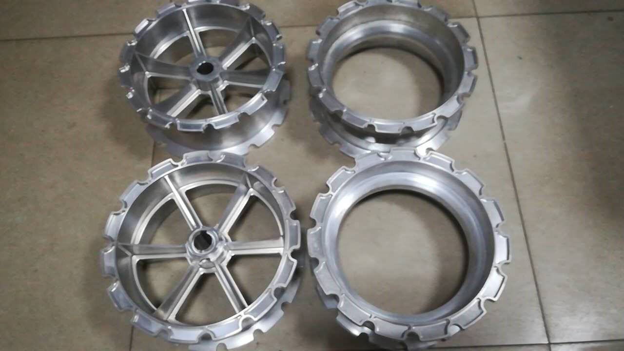
Processing steps are generally performed by china luminum cnc milling machining manufacturers utilizing endmills. Shell endmills can be utilized for roughing steps, however they normally produce vertical dividers with more unpleasant than-wanted surface completions. The equivalent is valid for roughing endmills. In the event that a shell endmill or roughing endmill is chosen for roughing, plan to leave enough material for wrapping up utilizing a standard endmill. To begin with, secure the cnc machining parts, select and mount the ideal cutting instrument, and figure and set a suitable axle RPM and feed rate (if power feed is accessible). These means disclose how to process a stage with a roughing and standard endmill in 4 axis cnc milling machine china utilizing the X-pivot to screen the width of the progression:

  • After mounting the roughing endmill, position the end inside around 1/16″ of the top surface of the square, much the same as when face processing.
  • Make sure the plume stop is against the micrometer changing nut and lock the plume.
  • Move the table so just around 1/8″ of the shaper is over the square, much the same as when face processing.
  • Start the shaft.
  • Raise the knee to ignite the highest point of the workpiece to set a reference for the profundity of the progression.
  • Set the micrometer collar on the knee wrench to”0″.
  • Move the X-pivot so the endmill is away from the workpiece.
  • Raise the knee to set the ideal profundity of cut and lock it set up.
  • Slowly get the table to ignite the finish of the part to set a reference for the width of the progression.
  • Set the micrometer collar or DRO for the X-pivot to “0.”
  • Move the seat so the endmill clears the workpiece, situating the instrument for ordinary processing.
  • Move the table to set cut width and lock.
  • Raise the knee to set cut profundity and lock. Recollect a few rules about cut profundity and width. On the off chance that the full breadth (or almost full width) of the endmill will be cutting, greatest profundity should be one-portion of the device distance across. Whenever cut profundity is past one-portion of the apparatus breadth, most extreme width should be around one-fourth of the device distance across.
  • Apply cutting liquid and utilize the seat to process the progression.
  • Return the seat to the starting position.
  • Repeat these means to unpleasant the progression inside about 0.015″ to 0.020″ of both the progression width and profundity measurements.
  • Remove the roughing endmill and mount a standard endmill.
  • Reset axle speed and feed varying.
  • Touch the endmill off the roughed vertical divider and the level surface.
  • Move the endmill away from the workpiece with the seat in cnc turning and milling metal machining factory work factory.
  • Move the table and raise the knee each about 0.005 “.
  • Take a traditional pass and afterward an ascension processing pass at those settings.
  • Stop the shaft and check both the progression width and profundity measurements.
  • Make last changes in accordance with the table and knee to set completion measurements for the progression.
  • Take a traditional pass and climb processing pass at those settings.
  • Take a spring traditional and climb processing pass to complete the progression. This article is from http://www.tinymachining.com

Tolerances Reference

Profile tolerances are regularly (however not generally) identified with another component, so their element control casings will often indicate datums. They are applied simply like the circularity and cylindricity particulars, however to non-cylindrical surfaces.

The profile of a line is like circularity. Everything cross segments of the surface require to be inside the predefined tolerance zone, yet they don’t all should be inside a similar tolerance zone. Just each cross area in turn can be examined.

The profile of a surface of cnc machining parts china is fundamentally the same as cylindricity. The whole surface must be inside the predefined tolerance zone. Everything cross segments of the surface require to be inside a similar tolerance zone. It could be reviewed at each point on a superficial level. Figure 3.1.36 shows include control outlines indicating profile of a line and profile of a surface, and it illustrates their implications.

Orientation Tolerances

Orientation tolerances are identified with different highlights, so their component control casings will determine datums. Parallelism implies that each point on a superficial level must be an equivalent good ways from the predetermined datum surface (equal) inside the given tolerance zone. Figure 3.1.37 shows an element control outline determining parallelism and illustrates its significance.

Orientation implies that an element (habitually a surface) must be at a 90-degree edge to the predefined datum (or datums) inside the given tolerance zone. Figure 3.1.38 shows an Orientation highlight control outline and illustrates the Orientation tolerance.

Precision is actually similar to Orientation however is utilized for rakish surfaces that are not 90 degrees. Figure 3.1.39 shows a component control outline determining rakishness and illustrates the precision tolerance.

Location Tolerances

Location tolerances are utilized to indicate the area of highlights identified with different highlights, so their component control casings will reference datums.

Concentricity looks at connection of the tomahawks of at least two round and hollow highlights. The whole element must be inside a barrel shaped tolerance zone. Concentricity isn’t utilized frequently on the grounds that it very well may be troublesome, tedious, and costly to review.

Position (or genuine position) is utilized to determine the focal point of highlights, for example, openings or spaces. Consequently, position include control outlines regularly contain more than one datum.

Recall that the significant standard of GD&T is its capacity to make it simpler to make satisfactory mating parts on account of more noteworthy tolerances. The position tolerance is an ideal model. As appeared in Figure 3.1.40, a customary +0.005′ direct, or organize, tolerance on a gap area makes a 0.010″ square tolerance zone. The focal point of the gap must be situated inside that square zone. On the off chance that the gap is focused at one of the outrageous corners of the square, it is more than 0.005 ” from the predefined print area. It is in reality out of position by 0.007″ and the tolerance zone over the edges of the square is 0.014″. Since that position is satisfactory, any area that is 0.007 ” from the print area ought to likewise be worthy, yet by traditional tolerance techniques, parts would be dismissed for china precision stamping parts manufacturers.

The location tolerances makes a circle that contacts those four corners and results in a round tolerance zone. China machining service is given some element control outlines for location tolerances.

Location Tolerance Modifiers and Bonus Tolerance

Sometimes, as the size of a section highlight changes inside its tolerance, to china high precision cnc bronze custom made parts suppliers, a position tolerance is allowed to change also. The area of round highlights is one model.

Sometimes, when a breadth expands, the area tolerance may increment. In different cases, when a measurement decreases, the area tolerance may increment. This expansion in tolerance is known as the reward tolerance. Three images called position tolerance modifiers are utilized to address circumstances like these. This article is from http://www.tinymachining.com/