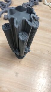
Two Strateges to Square

After the initial four sides have been processed square and equal, one of two strategies is utilized to square the two leftover sides of the china high precision cnc machining metal mechanical parts.

Strategy 1

  • The square can be mounted freely in the tight clamp with one end looking up.
  • The light emission strong square can be set on the bed of the tight clamp or on the machine table, and the side of the workpiece lined up with the cutting edge of the square.
  • After clipping, sensor stock can be utilized to check for holes between the vertical workpiece surface and the cutting edge of the square.
  • Mill the surface utilizing a similar face processing steps used to machine the initial four sides. This surface can be called Side E.
  • Remove the square from the tight clamp, deburr the sharp edges, and check for opposietness.
  • Place this recently machined surface down in the tight clamp and situated on equals so the contrary surface can be processed.
  • Machine a cleanup pass and check for parallelism with the lower part of the workpiece prior to processing to conclusive size. Once more, at whatever point conceivable, measure the work-piece without eliminating it from the tight clamp to dodge any arrangement or repositioning mistakes.

Strategy 2

Another strategy for squaring the closures is to mount the square in the tight clamp on equals with one end reaching out past the finish of the tight clamp jaws. The end would then be able to be machined by fringe processing utilizing an endmill by china edm machine manufacturers.

The length of the cutting bit of the endmill should be somewhat more than the thickness of the workpiece and the width should be enormous enough so it doesn’t flex under cutting tension. A decent practice is to restrict length to around multiple times the measurement of the instrument.

  • Mount the work in the tight clamp by putting it on equals and seating with a dead blow hammer.
  • Select and mount an appropriate endmill.
  • Calculate and set a suitable shaft speed and feed rate (if power feed is accessible).
  • Use the plume and knee to position the endmill vertically as appeared in china aluminium machined parts. Make sure to bring the plume stop against the micrometer changing nut and lock the plume.
  • The X-hub is ordinarily used to set profundity of cut, and the Y-pivot is utilized to play out the processing passes.
  • Conventional processing should be utilized to take roughing passes, and climb processing should be performed distinctly with a light cut for a completing pass, so remember that when situating the endmill toward the start of the cut. See precision machining parts suppliers china for an illustration of certain instances of how to position the endmill for regular and climb processing.
  • Start the shaft and carry the endmill into light contact with the edge of the workpiece utilizing the X-hub to “ignite” the device.
  • Seta”0″ reference utilizing the micrometer collar or DRO.
  • Use the Y-hub to move the endmill away from the part.
  • Set profundity of cut utilizing the X-pivot and afterward lock it set up to forestall development during the processing pass. Eliminate simply enough material to tidy up the surface on this first side.
  • Apply cutting liquid and draw in the force feed or move the Y-pivot physically to play out the ordinary processing pass.
  • Use the Y-pivot to criticism over the surface at a more slow rate to take a completing trip processing pass. high precision surface grinder manufacturers china shows these processing steps.
  • Remove the square from the tight clamp, deburr it, and check for square.
  • Place the square in the tight clamp with the furthest edge reaching out past the jaws and rehash the cycle to tidy up this last side.
  • Seta “O” on the micrometer collar or DRO to set up a reference position.
  • Machine roughing passes utilizing traditional processing inside about 0.010″ to 0.020″ of definite size utilizing the micrometer collar or DRO to set cut profundity.
  • Take an ascension processing pass of about 0.005″ to 0.010″and reevaluate size.
  • Take one final ordinary processing and climb processing pass to process the square to the ideal last measurement.
  • This article is from http://www.tinymachining.com

Holemaking Task

Holemaking tasks are performed on the vertical processing machine utilizing similar cutting devices and machining strategies utilized on the drill press for china metal custom 4 axis cnc machining high precision micro spare parts. Straight-shank cutting instruments are mounted in hurls and Morse tighten shank cutting devices are mounted in R-8 connectors intended to acknowledge Morse tightens. The significant advantage of performing holemaking tasks utilizing the vertical factory is the capacity to all the more correctly set up opening areas. Rather than moving the work on the table to adjust the axle to a crossing point of design lines or a punch mark, the work can be decisively moved utilizing the table and seat developments to adjust the work to the axle. The micrometer collars or an advanced readout (DRO) can likewise be utilized to make exact dividing between opening areas or among edges and opening areas.

When situating utilizing just micrometer collars, consistently pivot the handle a similar way to guarantee exact area. While altering course, go past the ideal perusing, at that point move the first way of movement to show up at the collar perusing.

Finding the Center of an Existing Part Feature

To locate the focal point of a current opening, a dial marker is frequently utilized to get china high precision cnc machining metal mechanical parts. Follow these means to locate the focal point of a current circular opening.

  • Visually find the axle in the focal point of the opening by moving the table and seat.
  • Mount a dial test pointer in the axle as appeared in metal milling machining parts china and bring down the plume so the marker contact point is inside the opening.
  • Place the shaft in unbiased and turn the marker so it is in accordance with either the X-or Y-hub, and move the contact point against the outside of the opening to preload the pointer.
  • Set the dial on the marker to zero by tenderly pivoting the pointer’s face.
  • Rotate the axle 180 degrees and note the course and measure of needle development.
  • Move the X-(or Y-) pivot one-a large portion of the distinction of the two readings so the needle moves back toward the underlying zero perusing. For instance, if the needle turns to one side until the needle stops at 0.020, the table must be moved until the needle moves back to one side and stops on 0.010.
  • Repeat the cycle for the different pivot.
  • After the shaft is found accurately, lock the table and saddle and reverify the TIR (all out marker perusing) while at the same time clearing the opening.
  • Adjust the two tomahawks varying until the ideal exactness is accomplished.
  • Set the micrometer collars or the DRO to a reference “0”position.

This technique can likewise be utilized to locate the focal point of a square inner opening to get the high-quality precision cnc machining parts. At the point when the shaft is focused in the opening, marker readings will be the equivalent at each side of the square. In the event that the inward opening is a square shape, the readings will be similar 180 degrees separated, yet the readings on the X-hub will be not quite the same as the readings on the Y-pivot. While demonstrating the bigger component of the square shape, the plume may should be withdrawn so the marker can be cleared to the contrary side.

On the off chance that a circular opening is excessively little for the pointer contact point, a pin gage can be put in the opening and the outside of the pin gage demonstrated rather than within surface of the opening. A similar strategy can be utilized to show the focal point of a round center or round workpiece.

This article is from http://www.tinymachining.com
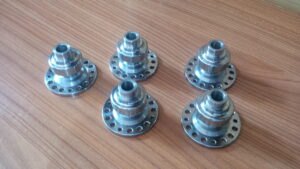
Collets

Arbor type processing cutters, for example, slitting saws and structure cutters have a straight opening through their middle with a solitary keyway. These cutters in cnc machined carbon fiber parts manufacturers must be made sure about onto a stub arbor for mounting in the machine shaft. Most vertical factory stub arbors accompany a R-8 shank. They contain a progression of spacers to oblige diverse width cutters. A locking nut or screw is situated on the finish to make sure about the cutting instrument. cnc carbon fibre cutting manufacturers use spacers on each side of the shaper and make certain to safely fix the cinching nut or screw.

Another choice for holding straight shank cutting instruments in the vertical factory is the R-8 collet appeared in precision cnc machining manufacturer. R-8 collets have an inside string in their back finishes to acknowledge the drawbar strings. At the point when the drawbar is fixed, the collet is pulled up into the shaft tighten, making the collet agreement and hold the cutting instrument.

Collets offer predominant runout control and the most limited projection from the axle nose of the entirety of the other toolholding gadgets. R-8 collets come in additions of 1/32″ and can just grow or agreement about 0.005 to 0.010′ above and beneath their stamped size.

Follow these means to introduce a straight shank apparatus utilizing a R-8 collet:

  • Place the machine shaft in one or the other low or high reach.
  • Clean the machine shaft tighten and the outside of the collet.
  • Partially embed the collet tenderly into the shaft until contact is felt with the axle key.
  • Rotate the collet until its space lines up with the axle key, and afterward embed the collet the remainder of the path into the axle.
  • Thread the drawbar into the collet by hand leaving around 1/16″ to 1/8″ of vertical collet development.
  • Insert the straight shank apparatus into the collet.
  • Apply the shaft brake to keep the axle from pivoting and fix the drawbar utilizing a fitting wrench.

Follow these means to eliminate an instrument mounted in a R-8 collet.

  • Place the axle in one or the other low or high reach.
  • Hold the shaft brake to keep the axle from turning.
  • Loosen the drawbar 1 to 2 turns with a proper wrench.
  • Hold the cutting apparatus with one hand and gently strike the highest point of the drawbar with a metal mallet to deliver the shape shank holder from the axle tighten. Most vertical processing machines have an apparatus that has a drawbar wrench toward one side and a metal mallet on the opposite end.
  • Do not totally unthread the drawbar prior to tapping with a sledge. This can harm the strings on both the drawbar and holder, and it can likewise cause the collet or potentially instrument to drop out of the shaft.
  • Remove the cutting device from the collet.
  • Unthread the drawbar the remainder of the best approach to eliminate the collet.

Clips require uncommon consideration since they generally (except for toe cinches) distend over the highest point of the work surface, and the potential for crash with cutting instruments is extremely high so as to get  china metal custom 4 axis cnc machining high precision micro spare parts.

This article is from http://www.tinymachining.com.