Two Strateges to Square

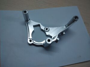
After the initial four sides have been processed square and equal, one of two strategies is utilized to square the two leftover sides of the china high precision cnc machining metal mechanical parts.

Strategy 1

  • The square can be mounted freely in the tight clamp with one end looking up.
  • The light emission strong square can be set on the bed of the tight clamp or on the machine table, and the side of the workpiece lined up with the cutting edge of the square.
  • After clipping, sensor stock can be utilized to check for holes between the vertical workpiece surface and the cutting edge of the square.
  • Mill the surface utilizing a similar face processing steps used to machine the initial four sides. This surface can be called Side E.
  • Remove the square from the tight clamp, deburr the sharp edges, and check for opposietness.
  • Place this recently machined surface down in the tight clamp and situated on equals so the contrary surface can be processed.
  • Machine a cleanup pass and check for parallelism with the lower part of the workpiece prior to processing to conclusive size. Once more, at whatever point conceivable, measure the work-piece without eliminating it from the tight clamp to dodge any arrangement or repositioning mistakes.

Strategy 2

Another strategy for squaring the closures is to mount the square in the tight clamp on equals with one end reaching out past the finish of the tight clamp jaws. The end would then be able to be machined by fringe processing utilizing an endmill by china edm machine manufacturers.

The length of the cutting bit of the endmill should be somewhat more than the thickness of the workpiece and the width should be enormous enough so it doesn’t flex under cutting tension. A decent practice is to restrict length to around multiple times the measurement of the instrument.

  • Mount the work in the tight clamp by putting it on equals and seating with a dead blow hammer.
  • Select and mount an appropriate endmill.
  • Calculate and set a suitable shaft speed and feed rate (if power feed is accessible).
  • Use the plume and knee to position the endmill vertically as appeared in china aluminium machined parts. Make sure to bring the plume stop against the micrometer changing nut and lock the plume.
  • The X-hub is ordinarily used to set profundity of cut, and the Y-pivot is utilized to play out the processing passes.
  • Conventional processing should be utilized to take roughing passes, and climb processing should be performed distinctly with a light cut for a completing pass, so remember that when situating the endmill toward the start of the cut. See precision machining parts suppliers china for an illustration of certain instances of how to position the endmill for regular and climb processing.
  • Start the shaft and carry the endmill into light contact with the edge of the workpiece utilizing the X-hub to “ignite” the device.
  • Seta”0″ reference utilizing the micrometer collar or DRO.
  • Use the Y-hub to move the endmill away from the part.
  • Set profundity of cut utilizing the X-pivot and afterward lock it set up to forestall development during the processing pass. Eliminate simply enough material to tidy up the surface on this first side.
  • Apply cutting liquid and draw in the force feed or move the Y-pivot physically to play out the ordinary processing pass.
  • Use the Y-pivot to criticism over the surface at a more slow rate to take a completing trip processing pass. high precision surface grinder manufacturers china shows these processing steps.
  • Remove the square from the tight clamp, deburr it, and check for square.
  • Place the square in the tight clamp with the furthest edge reaching out past the jaws and rehash the cycle to tidy up this last side.
  • Seta “O” on the micrometer collar or DRO to set up a reference position.
  • Machine roughing passes utilizing traditional processing inside about 0.010″ to 0.020″ of definite size utilizing the micrometer collar or DRO to set cut profundity.
  • Take an ascension processing pass of about 0.005″ to 0.010″and reevaluate size.
  • Take one final ordinary processing and climb processing pass to process the square to the ideal last measurement.
  • This article is from http://www.tinymachining.com

Tool Posts

For any machining parts manufacturers, the tool posts for quick tool change is very important. They should consider the convenience for usage and change. The speedy change apparatus post is considerably more helpful to use than the rocker-type post. The snappy change device post comprises of a T-nut, bracing stud, and device post. Snappy change apparatus posts are generally furnished with a dovetail that mates with a dovetail on a toolholder. The apparatus present is braced on the compound rest utilizing the T-nut and cinching stud. The handle moves a bracing system that locks and opens toolholders mounted on the post. A holder is slid onto the dovetail and the handle is pulled to bolt the holder to the post. Switching the handle opens the post so the holder can be taken out. China metal cnc machining parts suppliers shows a speedy change device post.

The speedy change apparatus present permits a few instruments on be preset in various holders. They can be rapidly and effectively changed by custom precision machined components factory without the need to reset their situations likewise with the rocker-type post and holder.

Snappy Change Toolholders

The dovetail-molded snappy change toolholders slide onto the coordinating dovetail on the brisk change posts. A few styles of holders are accessible. A few holders permit slicing instruments to be clipped by fixing screws, and others include incorporated apparatuses. China 3 axis cnc machining service manufacturers gives a few instances of brisk change holders. Instrument stature is set by moving the changing nut to raise or lower the situation of the holder on the apparatus post, as appeared in china 4 axis cnc machining.

Indexable Tool Posts

An indexable device post comprises of a F-nut, clipping stud, and a multi-sided apparatus block with either removable or necessary toolholders. The china high precision cnc bronze custom made parts manufacturers show some samples. This square can be stacked with different apparatuses all the while, at that point effortlessly pivoted and made sure about to situate the ideal instrument for machining. These apparatus posts regularly have detents, or scores, that permit them to be turned and afterward consistently and precisely situated in similar areas.

An indexable instrument post can hold different cutting devices, which can significantly lessen arrangement time. Those with vital toolholders may just hold four instruments and would require resetting of devices if in excess of four distinctive cutting devices were required. Others use the speedy change framework, so despite the fact that solitary a specific number of instruments might be mounted to the post at one time, many tools can be preset so they can be rapidly and handily eliminated and introduced back similarly situated.

To introduce, a T-nut is put into the T-space machined into the compound rest. The device present is cinched on the compound rest by fixing the stud into the T-nut. A switch situated on head of the instrument block is utilized to open the apparatus post, record it to the ideal position, and afterward lock it set up for machining. This article is from http://www.tinymachining.com.

Morse Taper

Numerous holemaking cutting devices more than 1/2″ in width have tighten shanks rather than straight shanks. The inside Morse tighten in the drill press axle can be utilized by the china precision parts factory for rough, quick, and exact direct mounting of tighten shank cutting instruments. Since numerous sizes of Morse tightens exist, connectors are accessible to change over the slicing apparatus shank to coordinate the drill press axle tighten size. Morse tighten sleeves increment the size of a device’s shank tighten and Morse tighten augmentation attachments can be utilized to decrease the size of a device’s shank tighten.

When amassing tightens, be certain that the drag and shank are both clean and burr free. The finish of Morse tightens utilized by tight tolerance precision machining supplier on holemaking instruments have a tang that must be lined up with a mating space in the getting bore. The shapes are self-holding and are amassed utilizing a speedy, intense movement. Weight from the penetrating activity further makes sure about the shapes together.

To eliminate a shape shank apparatus from the drill press axle, a wedge-formed drill float is embedded between the shapes through an opening in the shaft and daintily tapped with a mallet. The range edge of the float should look up and the level edge ought to be against the tang of the instrument. Continuously hold the mounted tooling by hand when isolating shapes so the instrument and machine table are not harmed when it discharges from the axle. It is a smart thought to put a wooden square between the apparatus and the worktable to prevent the instrument from falling.

Hold cutting apparatuses by the shank, not by the flutes, when mounting them in a drill press shaft, sleeve, or attachment to keep cuts from sharp edges.

Subsequent to eliminating devices from a drill press shaft, promptly eliminate the float from the axle. Beginning the machine shaft will fiercely toss the float and can cause genuine injury.

Straight-Shank Toolholding

Straight-shank tooling must be mounted in a drill toss. Drill tosses are frequently furnished with Morse tighten shanks and are mounted in and taken out from the drill press axle in a similar way as tighten shank instruments. A few unique sorts of tosses exist for various applications. Keyed drill hurls are frequently called Jacobs-type tosses and are accessible in various sizes with different grasping limits. A few models can grasp as little as a couple of thousandths of an inch, while others can hold straight-shank apparatuses up to around 1″ in measurement. Most drill press hurls have three jaws that must be fixed with an extraordinary throw key. Eliminate the hurl key from the drill toss following mounting instruments in or eliminating them from the throw. Beginning the machine shaft will viciously toss the key and can cause genuine injury.


Drill throws are additionally accessible in keyless styles that can be fixed by turning a knurled neckline by hand without the utilization of any apparatuses. Keyless throws empower instruments to be changed all the more rapidly.

Forte hurls are additionally accessible for little gap penetrating. The pin tight clamp hurl is a miniature drill toss that has an a lot slimmer plan, has a littler limit, and will empower little bores to run more genuine than a bigger toss.

Delicate miniature drilling connectors are additionally accessible for little opening penetrating. The preferred position with this kind of drill is that weight can be delicately applied by china cnc 4 axis machining supplier to the bore under fine finger tension. These spring-stacked connectors permit elevated levels of affect-ability when penetrating with delicate little distance across boring apparatus.

This article is from http://www.tinymachining.com
Machining Drawing Importance

A significant aptitude required for accomplishment in the machining field for precision cnc machining parts manufacturers is the capacity to decipher designing drawings, or prints. Building drawings show the sizes and states of segments and their particular highlights, for example, openings, spaces, or surfaces.

Regardless of how skilled you are at performing machining tasks, in the event that you can’t appropriately decipher these drawings, you won’t have the option to deliver machined segments freely or efficiently inside required determinations.

Machining drawings can go from basic hand-drawn representations to complex, PC produced prints. They are delivered in a standard arrangement that empowers mechanics anyplace to get them. Printed drawing sizes run from 8.5x 11 up to 34 x 44 inches. Drawings for complex segments may contain a few sheets.

Machining drawings are comprised of a few segments. These components make up a standard arrangement of perspectives, lines, and images that give significant data about required particulars for machined segments.

One significant part of a drawing is the title square. The title square incorporates data, for example, the part name and number, tolerances, scale, material that the part ought to be produced using, and any necessary warmth treatment. Architect and  drafts person names and drawing creation date are additionally normally included. A past filled with modifications, or changes, can be appeared over the title hinder also, in a container regularly called the correction square. Updates remember changes for measurements, material, tolerance or surface completion. Every correction ought to have a portrayal, a date, and the initials of the individual who endorsed the amendment. An update square may likewise be appeared in the upper-right corner of a print. It is acceptable practice to check for updates to guarantee the print particulars are current.

Scale is the size of a real article identified with its size drawn on a print. Parts that are attracted to genuine size on paper are full scale. This scale can be appeared as 1:1. The 1:1 implies that 1″ on the attracting is equivalent to 1″ on the real part. The drawing is a similar size as the part.

Enormous items are every now and again drawn littler than genuine size to make drawings simpler to utilize. On the off chance that an item is drawn a large portion of its real size, the scale can be appeared as 1/2, 1:2, or 1/2″ = 1″. These all imply that 1/2″ on the attracting is equivalent to 1″ on the real part. The drawing is littler than the genuine part.

Little articles are frequently drawn bigger by precision parts manufacturers china than real size to show subtleties that may be too hard to even think about seeing in the event that they were attracted to genuine size. For instance, if an item is drawn twice its genuine size, the scale can be appeared as 2/1, 2:1, 2X, or 2″ = 1″. These all imply that 2″ on the drawing is equal to 1″ on the genuine part. The drawing is bigger than the genuine part.

In all cases, paying little heed to scale, drawing measurements indicated are genuine part estimates. Some of the time a print may have a bill of materials. A bill of materials can either list the crude materials used to make the machined part or rundown segments that are amassed to create the part indicated on the print. An example designing drawing with the title square, modification square.

This article is from http://www.tinymachining.com.