Stringing on a machine is finished with a lower axle speed than would be utilized for turning comparable measured breadths. This is accomplished for two reasons. To start with, stringing requires a lot of hardware contact with the workpiece and prattle might be forestalled by a lower axle speed. Second, stringing requires a lot of administrator consideration since the apparatus propels so rapidly and the half-nut switch must be locked in and separated at unequivocally the right time. Since the carriage feed is straightforwardly connected to the axle revolution, running the shaft at a lower speed will give the administrator more opportunity to draw in and separate the half-nut switch. An axle speed around one-fourth of a turning speed for a similar distance across is a decent beginning stage.
Continuously make a preliminary pass with the instrument far away from the work, headstock, and tailstock to check the pace of carriage movement. On the off chance that the rate is excessively quick to securely connect with and separate the half-nut switch, lessen axle speed likewise.
Introducing and Aligning the Cutting Tool
There are a couple of various styles of cutting instruments for machining outer strings. A HSS device spot can be ground on a platform processor to the best possible string structure. Its sides must have side freedom points to cut and forestall scouring. Brazed carbide instruments can be bought with the ideal string structure and leeway points.
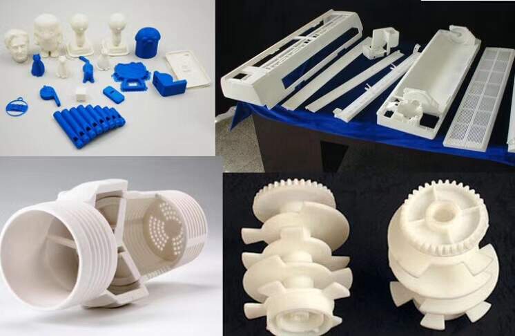
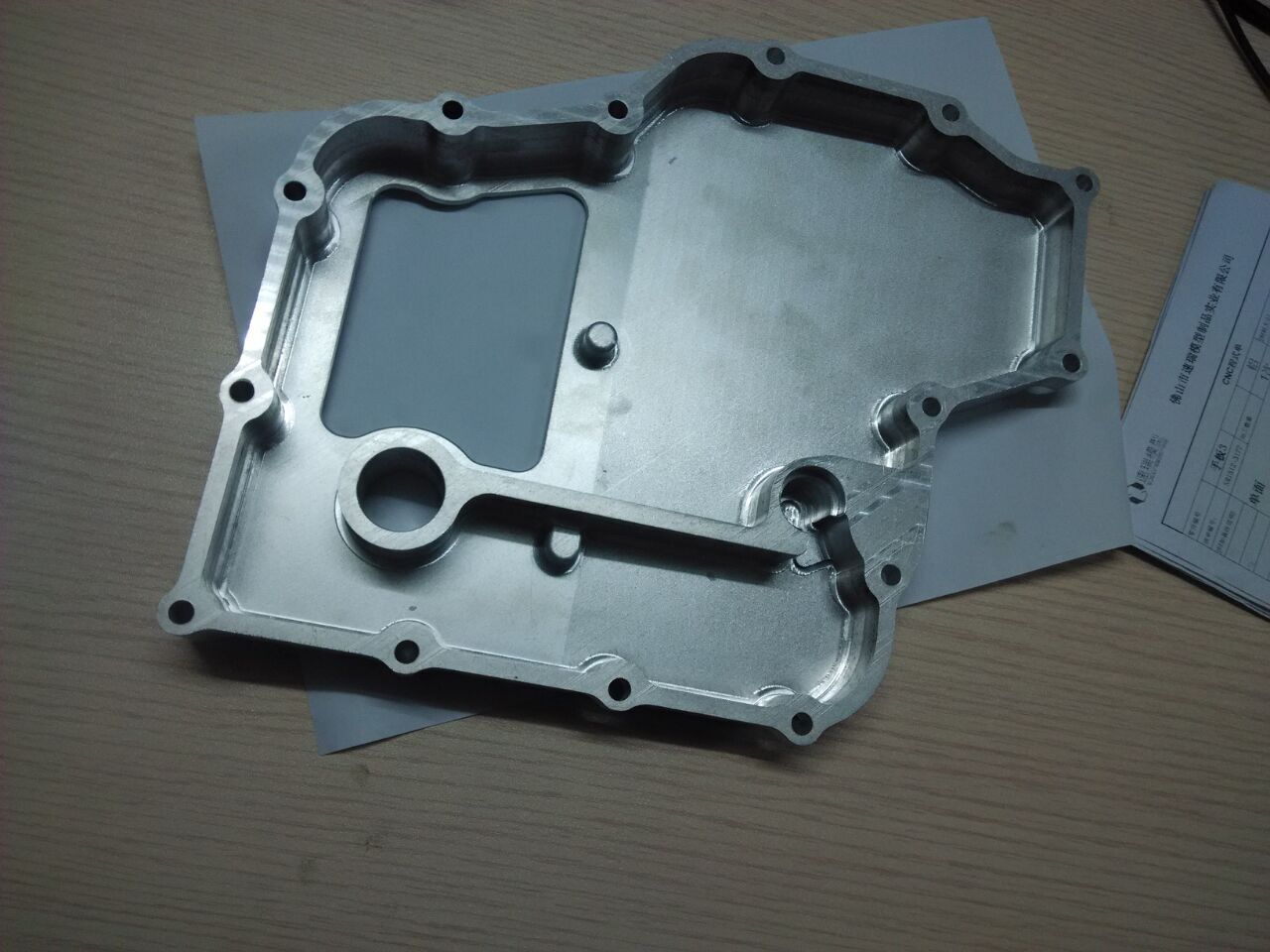
Carbide embedded stringing instruments are likewise accessible from many cutting-device makers. china metal custom 4 axis cnc machining high precision micro spare parts shows a few instances of outer string cutting instruments. When cutting inside strings, toolholders like those utilized for drilling are utilized to hold the cutting apparatus with the goal that it tends to be stretched out into the opening in the workpiece.
china high precision cnc machining metal mechanical parts shows some various kinds of inner stringing devices. With both outer and inside instruments, consistently make certain to mount the apparatus with minimal measure of shade conceivable to guarantee most extreme inflexibility. Inner stringing devices are particularly dependent upon unbending nature issues on account of the slim shank important to stretch out into an opening.
Continuously select the biggest breadth inner stringing device bar that will find a way into the opening and still give enough leeway to withdraw the apparatus from the string groove toward the finish of the pass. The arrangement of the string slicing instrument’s structure to the workpiece is significant.
- Place the stringing device in a holder and change the apparatus to the right stature. The stature of the slicing instrument should be set at the part’s middle line similarly with respect to turning and exhausting activities.
- A little gage called a middle gage (once in a while alluded to as a fishtail gage) is utilized to appropriately adjust the stringing apparatus. china high precision cnc bronze custom made parts manufacturers shows a middle gage.
- Hold the middle gage against the side of the workpiece surface.
- Bring the apparatus near one of the side “V”- grooves in the middle gage by moving the cross slide.
- Adjust the apparatus position until the tip fits appropriately into the “V”- groove in the middle gage, as appeared in china cnc 4 axis machining suppliers. This will find the bleeding edges of the stringing apparatus opposite to the workpiece.
- Tighten the toolholding gadget and reevaluate with the middle gage to guarantee the apparatus didn’t move during fixing. This article is from http://www.tinymachining.com