Tool Posts

For any machining parts manufacturers, the tool posts for quick tool change is very important. They should consider the convenience for usage and change. The speedy change apparatus post is considerably more helpful to use than the rocker-type post. The snappy change device post comprises of a T-nut, bracing stud, and device post. Snappy change apparatus posts are generally furnished with a dovetail that mates with a dovetail on a toolholder. The apparatus present is braced on the compound rest utilizing the T-nut and cinching stud. The handle moves a bracing system that locks and opens toolholders mounted on the post. A holder is slid onto the dovetail and the handle is pulled to bolt the holder to the post. Switching the handle opens the post so the holder can be taken out. China metal cnc machining parts suppliers shows a speedy change device post.

The speedy change apparatus present permits a few instruments on be preset in various holders. They can be rapidly and effectively changed by custom precision machined components factory without the need to reset their situations likewise with the rocker-type post and holder.

Snappy Change Toolholders

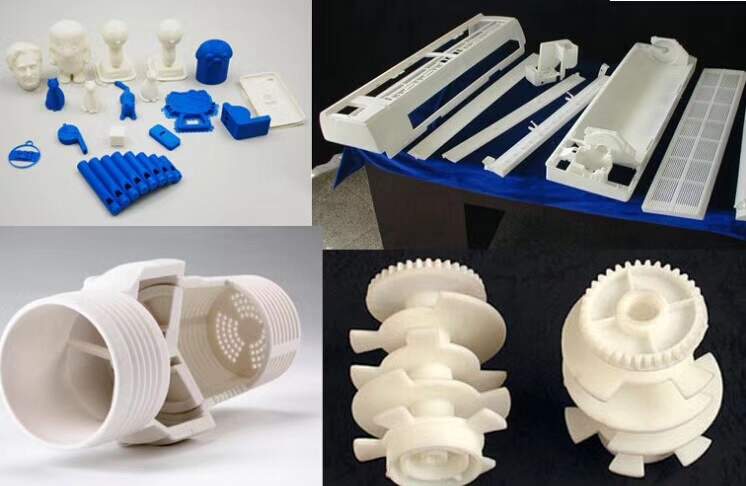
The dovetail-molded snappy change toolholders slide onto the coordinating dovetail on the brisk change posts. A few styles of holders are accessible. A few holders permit slicing instruments to be clipped by fixing screws, and others include incorporated apparatuses. China 3 axis cnc machining service manufacturers gives a few instances of brisk change holders. Instrument stature is set by moving the changing nut to raise or lower the situation of the holder on the apparatus post, as appeared in china 4 axis cnc machining.

Indexable Tool Posts

An indexable device post comprises of a F-nut, clipping stud, and a multi-sided apparatus block with either removable or necessary toolholders. The china high precision cnc bronze custom made parts manufacturers show some samples. This square can be stacked with different apparatuses all the while, at that point effortlessly pivoted and made sure about to situate the ideal instrument for machining. These apparatus posts regularly have detents, or scores, that permit them to be turned and afterward consistently and precisely situated in similar areas.

An indexable instrument post can hold different cutting devices, which can significantly lessen arrangement time. Those with vital toolholders may just hold four instruments and would require resetting of devices if in excess of four distinctive cutting devices were required. Others use the speedy change framework, so despite the fact that solitary a specific number of instruments might be mounted to the post at one time, many tools can be preset so they can be rapidly and handily eliminated and introduced back similarly situated.

To introduce, a T-nut is put into the T-space machined into the compound rest. The device present is cinched on the compound rest by fixing the stud into the T-nut. A switch situated on head of the instrument block is utilized to open the apparatus post, record it to the ideal position, and afterward lock it set up for machining. This article is from http://www.tinymachining.com.

Machining Drawing Importance

A significant aptitude required for accomplishment in the machining field for precision cnc machining parts manufacturers is the capacity to decipher designing drawings, or prints. Building drawings show the sizes and states of segments and their particular highlights, for example, openings, spaces, or surfaces.

Regardless of how skilled you are at performing machining tasks, in the event that you can’t appropriately decipher these drawings, you won’t have the option to deliver machined segments freely or efficiently inside required determinations.

Machining drawings can go from basic hand-drawn representations to complex, PC produced prints. They are delivered in a standard arrangement that empowers mechanics anyplace to get them. Printed drawing sizes run from 8.5x 11 up to 34 x 44 inches. Drawings for complex segments may contain a few sheets.

Machining drawings are comprised of a few segments. These components make up a standard arrangement of perspectives, lines, and images that give significant data about required particulars for machined segments.

One significant part of a drawing is the title square. The title square incorporates data, for example, the part name and number, tolerances, scale, material that the part ought to be produced using, and any necessary warmth treatment. Architect and  drafts person names and drawing creation date are additionally normally included. A past filled with modifications, or changes, can be appeared over the title hinder also, in a container regularly called the correction square. Updates remember changes for measurements, material, tolerance or surface completion. Every correction ought to have a portrayal, a date, and the initials of the individual who endorsed the amendment. An update square may likewise be appeared in the upper-right corner of a print. It is acceptable practice to check for updates to guarantee the print particulars are current.

Scale is the size of a real article identified with its size drawn on a print. Parts that are attracted to genuine size on paper are full scale. This scale can be appeared as 1:1. The 1:1 implies that 1″ on the attracting is equivalent to 1″ on the real part. The drawing is a similar size as the part.

Enormous items are every now and again drawn littler than genuine size to make drawings simpler to utilize. On the off chance that an item is drawn a large portion of its real size, the scale can be appeared as 1/2, 1:2, or 1/2″ = 1″. These all imply that 1/2″ on the attracting is equivalent to 1″ on the real part. The drawing is littler than the genuine part.

Little articles are frequently drawn bigger by precision parts manufacturers china than real size to show subtleties that may be too hard to even think about seeing in the event that they were attracted to genuine size. For instance, if an item is drawn twice its genuine size, the scale can be appeared as 2/1, 2:1, 2X, or 2″ = 1″. These all imply that 2″ on the drawing is equal to 1″ on the genuine part. The drawing is bigger than the genuine part.

In all cases, paying little heed to scale, drawing measurements indicated are genuine part estimates. Some of the time a print may have a bill of materials. A bill of materials can either list the crude materials used to make the machined part or rundown segments that are amassed to create the part indicated on the print. An example designing drawing with the title square, modification square.

This article is from http://www.tinymachining.com.