Holemaking Task

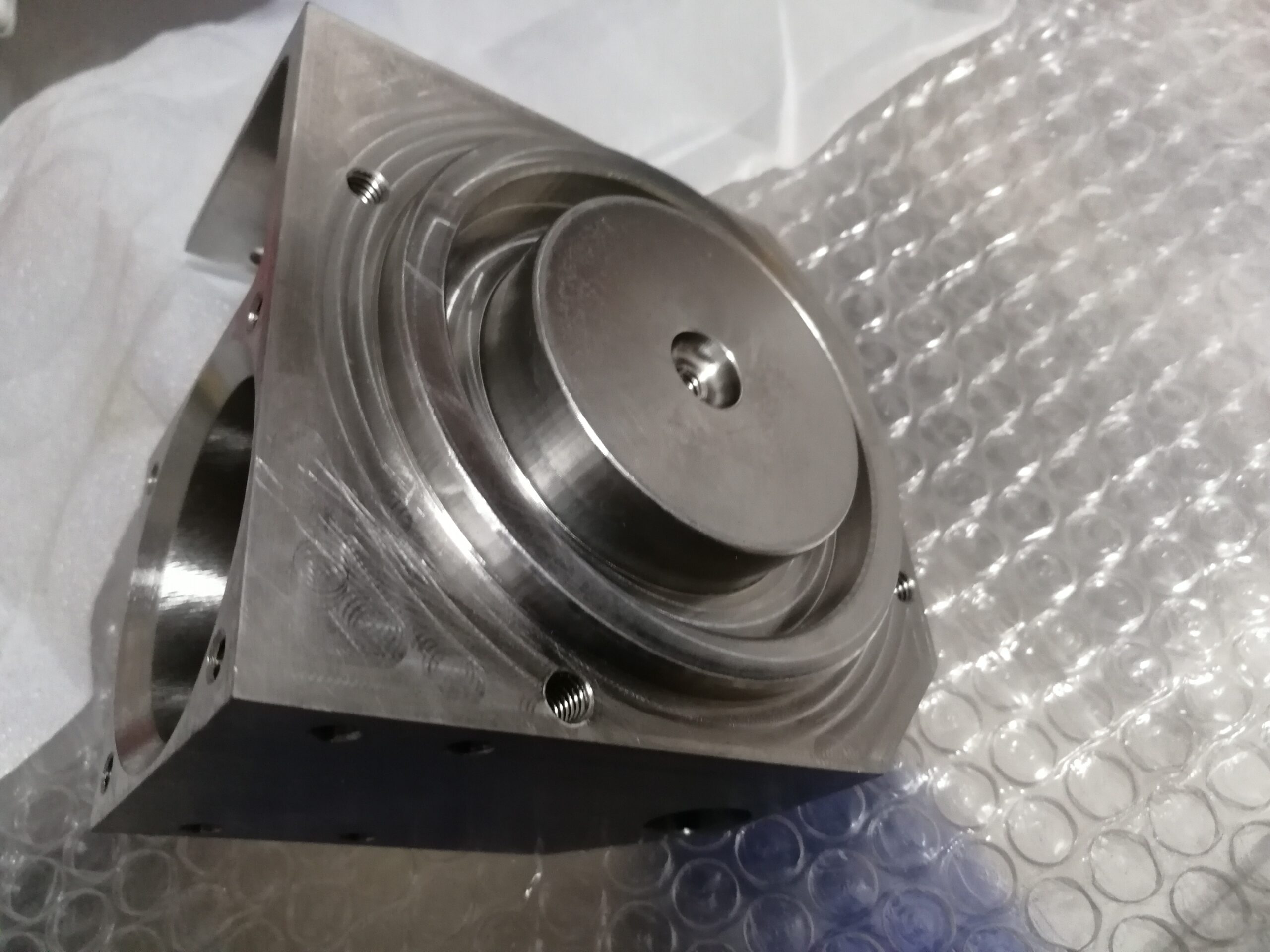
Holemaking tasks are performed on the vertical processing machine utilizing similar cutting devices and machining strategies utilized on the drill press for china metal custom 4 axis cnc machining high precision micro spare parts. Straight-shank cutting instruments are mounted in hurls and Morse tighten shank cutting devices are mounted in R-8 connectors intended to acknowledge Morse tightens. The significant advantage of performing holemaking tasks utilizing the vertical factory is the capacity to all the more correctly set up opening areas. Rather than moving the work on the table to adjust the axle to a crossing point of design lines or a punch mark, the work can be decisively moved utilizing the table and seat developments to adjust the work to the axle. The micrometer collars or an advanced readout (DRO) can likewise be utilized to make exact dividing between opening areas or among edges and opening areas.

When situating utilizing just micrometer collars, consistently pivot the handle a similar way to guarantee exact area. While altering course, go past the ideal perusing, at that point move the first way of movement to show up at the collar perusing.

Finding the Center of an Existing Part Feature

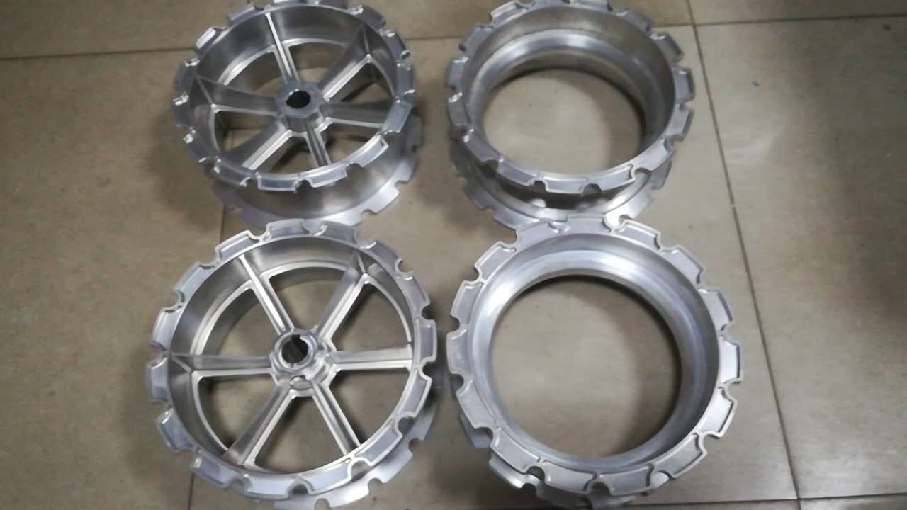
To locate the focal point of a current opening, a dial marker is frequently utilized to get china high precision cnc machining metal mechanical parts. Follow these means to locate the focal point of a current circular opening.

  • Visually find the axle in the focal point of the opening by moving the table and seat.
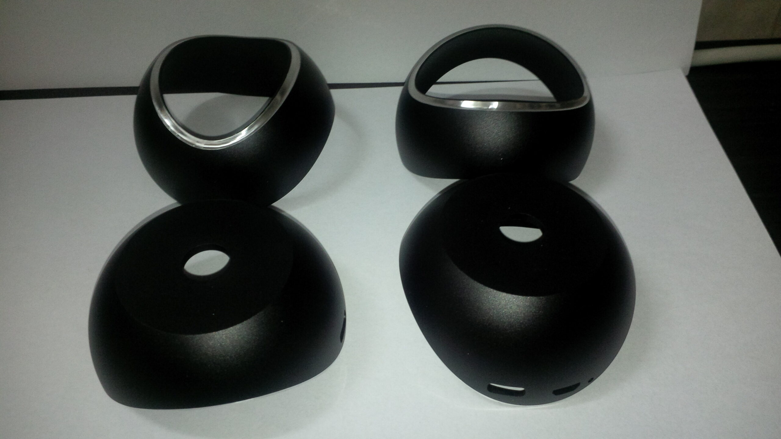
  • Mount a dial test pointer in the axle as appeared in metal milling machining parts china and bring down the plume so the marker contact point is inside the opening.
  • Place the shaft in unbiased and turn the marker so it is in accordance with either the X-or Y-hub, and move the contact point against the outside of the opening to preload the pointer.
  • Set the dial on the marker to zero by tenderly pivoting the pointer’s face.
  • Rotate the axle 180 degrees and note the course and measure of needle development.
  • Move the X-(or Y-) pivot one-a large portion of the distinction of the two readings so the needle moves back toward the underlying zero perusing. For instance, if the needle turns to one side until the needle stops at 0.020, the table must be moved until the needle moves back to one side and stops on 0.010.
  • Repeat the cycle for the different pivot.
  • After the shaft is found accurately, lock the table and saddle and reverify the TIR (all out marker perusing) while at the same time clearing the opening.
  • Adjust the two tomahawks varying until the ideal exactness is accomplished.
  • Set the micrometer collars or the DRO to a reference “0”position.

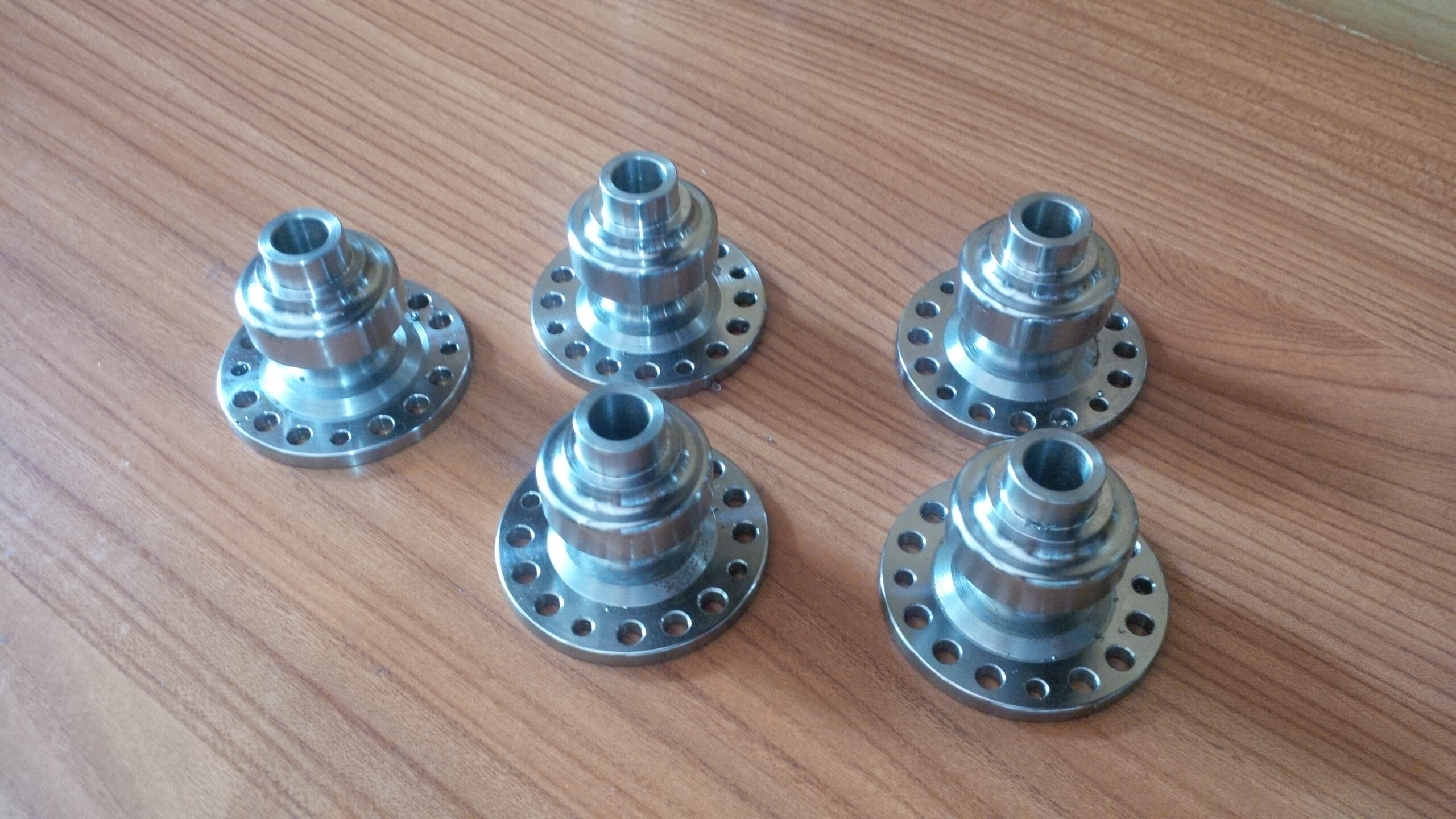
This technique can likewise be utilized to locate the focal point of a square inner opening to get the high-quality precision cnc machining parts. At the point when the shaft is focused in the opening, marker readings will be the equivalent at each side of the square. In the event that the inward opening is a square shape, the readings will be similar 180 degrees separated, yet the readings on the X-hub will be not quite the same as the readings on the Y-pivot. While demonstrating the bigger component of the square shape, the plume may should be withdrawn so the marker can be cleared to the contrary side.

On the off chance that a circular opening is excessively little for the pointer contact point, a pin gage can be put in the opening and the outside of the pin gage demonstrated rather than within surface of the opening. A similar strategy can be utilized to show the focal point of a round center or round workpiece.

This article is from http://www.tinymachining.com

Roughing and Finishing

Roughing and Finishing

In machine tasks, and all machining, there is harsh cutting and complete the process of cutting. The reason for unpleasant cutting, or roughing, is to eliminate however much material as fast as could be expected to draw near to the ideal size. There is little worry for making a smooth surface. Roughing utilizes more slow cutting velocities, more profound cuts, and higher feed rates.

Subsequent to roughing, complete the process of cutting, or completing, is utilized to deliver a smoother surface and carry the part to the last wanted size. Completing utilizations higher cutting rates, lighter cuts, and lower feed rates. cnc precision machining companies sums up roughing and completing and the connection among roughing and completing and profundity of Cut, speed, and feed.

Machining Time Calculation

It might be imperative to appraise the time needed to play out a machine activity or tasks. This is indispensable while machining huge parts or enormous quantities of parts. Machining time can be determined by china 4 axis cnc machining utilizing the accompanying equation. The accompanying models are outrageous and may not be normal, yet they show the significance of having the option to figure assessed machining time.

GENERAL LATHE SAFETY

Like any machine instrument, the machine can be extremely risky, however by watching a couple of fundamental precautionary measures, safe activity can be guaranteed. Explicit wellbeing notes are appeared all through this unit, yet following are a few insurances that ought to be seen during cnc lathe machining all kinds of precision metal parts factory.

cof
  • Always wear ANSI Z87 appraised security glasses while working a machine.
  • Wear suitable hard-soled work shoes.
  • Wear short sleeves or move up long sleeves past the elbows.
  • Do not wear any free attire that can become trapped in moving machine parts.
  • Remove watches, rings, and other adornments.
  • Secure long hair so it can’t get tangled in moving machine parts.
  • Make sure all machine monitors and covers are set up before working any machine.
  • Avoid expanding long workpieces past the left finish of the headstock.
  • Never work a machine that is bolted out or labeled out or eliminate someone else’s lock or tag.
  • When working a machine, remain zeroed in on the machine. Try not to get diverted by different exercises or converse with others.
  • Never leave the machine while it is running.
  • Do not let others change work, device, or machine settings and don’t change others’ arrangements.
  • Avoid quickly and strongly moving cutting instruments into the workpiece. This can break devices and toss sharp parts toward the administrator. Little distance across and short workpieces can likewise be pulled from the pivoting workholding gadget.
  • Never contact a workpiece or workholding gadget that is turning or endeavor to stop a machine axle by hand or with a cloth. Permit the axle to stop all alone.
  • Always shut off the axle and let it reach a stand-still before changing workholding or toolholding gadgets, to take estimations, or to clean the machine.
  • Remove chips from the workpiece and device utilizing a brush, forceps, or a chip snare simply after the shaft has reached a stand-still. Never eliminate chips by hand.
  • Never utilize packed air to clean chips, garbage, and cutting liquids from the machine.
  • This article is from http://www.tinymachining.com

Machining Parts

Oil-based cutting liquids comprise principally of oil or farming based oils, for example, soy or vegetable. Before, creature oils were utilized, yet they are infrequently utilized today since they will in general turn rank, breed microorganisms, and produce solid smells.

Straight 0ils

Straight oils (regularly called cutting oils) are utilized generally for light-obligation, momentary activities and on nonferrous metals used by precision machining parts made in china. They work very well on aluminum and magnesium amalgams. For heavier activities and when prepares are machined, fixings are added to improve the oil’s exhibition. One regular added substance is known as a wetting specialist. Wetting specialists assist oil with adhering to the instrument and workpiece. Fixings called outrageous weight added substances, for example, sulfur and chlorine, improve lubricity to diminish grinding. These sulfurized and chlorinated cutting oils are phenomenal decisions for activities, for example, driling and tapping where there is critical surface contact between the cutting instrument and workpiece.

Straight oils are anything but difficult to keep up on the grounds that they don’t disintegrate, yet they are genuinely costly. They can likewise make aggravation or hurtful fog or smoke, so a few controls might be expected to give satisfactory ventilation.

Solvent Oils

Solvent oils are like straight oils yet contain added substances that permit them to be joined with water. They are additionally called emulsifiable or water-miscible oils. The oil doesn’t really disintegrate in water, however is emulsified. This implies exceptionally little oil beads are suspended in the water. The subsequent mix is utilized as the cutting liquid. A wide range of equations of dissolvable oils are accessible. They are generally utilized for light-to medium-obligation factory and machine procedure on both ferrous and nonferrous metals. The solvent oil looks simply like a straight cutting oil at the same time, when blended in with water, it has a smooth appearance.

Solvent oils give higher cooling rates than straight oils on account of the water part. As a result of the oil segment, these cutting liquids despite everything give great lubricity and imperviousness to rust for workpieces and machine parts, however not in the same class as straight oils. Different added substances help the oil to stick to devices and workpieces simply like with straight oils. Since water is a favorable place for microscopic organisms, these liquids must be kept up appropriately so they don’t crumble and get malodorous.

Synthetic Based Cutting Fluids

Synthetic based cutting liquids, as the name states, depend on synthetic compounds and contain next to no or no oil. Both of the two fundamental sorts are blended in with water like solvent oils.

Engineered materials

Engineered materials contain no oil items and give the most significant level of cooling of every cutting liquid in light of the water and their substance cosmetics. Since they contain no oil, nonetheless, they don’t give similar degrees of lubricity as oil-based liquids. Appropriate water/engineered liquid focus levels must be checked intently when china cmc machining parts. In the event that the blend is excessively lean (a lot of water in the blend), erosion can without much of a stretch happen on workpieces and apparatus. They are likewise handily debased by greasing up oils from machine instruments, which makes them more hard to keep up. Engineered materials are likewise rather costly to auto parts cnc make manufacturers china. Various recipes of engineered materials are accessible for various procedure on both ferrous and nonferrous metals, however they are especially appropriate for accuracy crushing tasks in light of the high temperatures made by those cycles.

Semi-Synthetics

Semi-artificial materials are goes between solvent oils and engineered materials. They give preferable cooling over dissolvable oils, however not as high a level as unadulterated artificial materials. Due to their oil content, they grease up superior to unadulterated engineered materials, yet not just as straight or dissolvable oils.

Since semi-engineered materials are blended in with water, focus levels must be firmly observed, likewise with unadulterated engineered materials, to forestall erosion. Various recipes are accessible for various tasks including both ferrous and nonferrous metals. Semi-fabricated materials are the absolute most generally utilized cutting liquids for CNC machine and plant activities by precision cnc machining manufacturer.

This is from http://www.tinymachining.com/.


Brinell Hardness Scales used in Machining

To make china high precision cnc machining metal mechanical parts, it may use the Brinell hardness scales. The Brinell hardness scale is most generally used to assign hardness of nonferrous metals and prepares before machining and warmth treatment. Brinell hardness analyzers make a space on a bit of material with a 10-mm-width tungsten carbide ball. (Materialsother than metals can be tried utilizing a 5-mm ball.)

A 500-kg, 1500-kg, or 3000-kg weight or burden is utilized to press the ball into the material relying upon the material sort being tried. Harder materials require the utilization of heavier loads. After a hold up of 10-30 seconds, the heap is evacuated and the ball is withdrawn. The breadth of the impression is then contribution to a standard equation to figure the Brinell hardness number.

Brinell hardness numbers are contracted as either HB (Hardness Brinell) or BHN.

Prepares would by and large be tried utilizing the 3000-kg load. Brinell hardness numbers for prepares normally run from around 100 for delicate low-carbon prepares to more than 700 for completely solidified instrument prepares.

Performing Brinell Hardness Testing

There are numerous varieties of Brinell hardness analyzers, however two essential highlights can be utilized to order them. Like Rockwell analyzers, the main contrast is whether the analyzer is an open circle or shut circle type. This alludes to how the heap is applied. Open-circle type analyzers use loads or water powered strain to constrain the ball into test parts.

Shut circle analyzers utilize a microchip controlled engine to drive the ball into the material being tried. Another distinction identifies with how the space is estimated. The standard kind of analyzer performs just the activity of making the space. After the space is made, it should then be estimated with a Brinell magnifying instrument and the BHN determined utilizing the standard recipe. The second sort of analyzer plays out the test, consequently gauges the space, and yields the HB number on a gage or readout.

Before the hardness test is played out, the example to be tried must be perfect and liberated from oxidation and scale. This should be possible by machining, documenting, or cleaning with rough paper. On the off chance that there is oxidation, surface stamps, or knocks, bogus readings can result. A perfect surface additionally makes it simpler to quantify the space if the test is done on a manual analyzer.

The cnc precision machining companies playing out a Brinell hardness test is like playing out a Rockwell test. Here are the essential advances. Allude to the producer’s guidelines for insights concerning a particular model.

  1. Load the test part on the iron block and preclamp by raising the hoisting screw.
  2. Set the power of the significant burden. Contingent upon the model, this will be finished by changing water driven or gaseous tension, insalling the best possible loads, or setting an electronic control.
  3. Apply the heap. Contingent upon the model, this is finished by pulling a switch to apply the heap through water driven or pneumatic stress, flipping a switch to deliver the weight, or squeezing a catch on the electronic control. Most models will apply the heap, delay for a preset measure of time, and afterward withdraw the heap.
  4. Unclamp the example part by bringing down the hoisting screw.

On manual models, measure the space with a Brinell magnifying instrument, and afterward utilize the Brinell equation to compute the BHN. On programmed models, basically read the BHN on the showcase of the control.

This article is from http://www.tinymachining.com/.

Tiny Machining QC

The testing plan tells what number of or potentially how frequently to investigate measurements. A review plan determines what measurements to assess and what estimating instruments and procedures to use during examination. Much the same as procedure plans and examining plans, investigation plans can be totally different from organization to organization, however they all achieve a similar errand. Formal review plans are commonly utilized in high precision CNC machining parts or other creation conditions where enormous quantities of similar parts are machined or when complex shapes are delivered.

Determination of Critical Dimensions

The main assignment while making a review plan is determination of basic measurements for cnc machining suppliers. The meaning of a basic measurement is not entirely clear, however regularly they are measurements with the littlest or most impenetrable tolerances.

Another highlight consider is whether various activities or numerous machines are utilized to machine a section. Assuming this is the case, connections between measurements delivered by various activities might be called basic on account of varieties in how the part is made sure about during those tasks. A basic measurement may likewise be one that adjusts mating parts. On the off chance that diverse cutting instruments perform cnc machining manufacturing, the first and additionally last measurement delivered by each apparatus may likewise be viewed as basic to be certain that each device is performing alright to meet print resistances.

Determination of Measuring Tools and Procedures

When choices are made on basic measurements, estimating instruments and methodology must be chosen. Apparatus decision and investigation techniques rely upon the resilience of the measurement being examined. Think about a direct measurement with a resilience or admissible variety of 0.0001″. Positively a standard would never gauge precisely enough to assess this resilience. A vernier or dial caliper would not be reasonable either since their scales just read to 0.001″. Indeed, even a micrometer with a vernier scale would be faulty. Despite the fact that its scale peruses to 0.0001″, the worry would be that the measurement probably won’t be estimated reliably each time. On account of a 0.0001 ” resilience, a test marker, gage squares, and surface plate may be the most ideal decision. Then again, if a resilience were 1/16″, a standard would be adequate and utilization of a dial test pointer, gage squares, and surface plate would require considerably more time and exertion than required.

That would be wasteful, superfluous, and excessively expensive. The report advises what number of parts to investigate and when, just as what measurements to examine and the apparatuses and techniques to play out the examination. It likewise gives space to the investigator’s initials and to record estimations, dates, and times. The subgroup synopsis segments demonstrating normal and range will be examined quickly.

Statistical Process Control (SPC)

Statistical procedure control (SPC) is an advanced technique for following variety in sizes of machined parts. SPC utilizes the measurements determined in an investigation plan from the example parts delineated in an examining plan. SPC plots information on two sorts of outlines to examine patterns to a limited extent variety. They are called control outlines. This data assists with foreseeing the consistency of an activity and aides changes in accordance with the activity before it begins to create parts outside of resistances.

SPC programming can naturally make these diagrams by contributing estimation information. The information port on some estimating devices (normally computerized models) can be associated with a unique link to a PC running SPC programming. At that point estimations can be sent to the product and be consequently prepared for making of these outlines.

This article is from www.tinymachining.com