collet blocks

One basic activity is to process a square on a tube shaped workpiece utilizing a square collet block. Here is an illustration of how to process a/2″ square on a 3%4″ distance across workpiece.

  • First decide profundity of slice for the pads to be machined. Take away the ideal distance across the square from the earliest starting point measurement. So 34-V2 = V4 or 0.250. A big part of that sum should be machined from each side, so 0.125″ should be eliminated at four areas 90 degrees separated.
  • Mount the 3%”diameter workpiece in the square collet block.
  • Mount the square in a processing tight clamp. Since the square should be eliminated from the tight clamp, pivoted, and remounted in the tight clamp, utilizing a workstop is useful.
  • Mount a cutting apparatus in the shaft, at that point figure and set axle RPM.
  • Position the plume with the micrometer changing nut against the stop so the apparatus is around 1/16″ over the workpiece, and afterward lock the plume.
  • Position the apparatus for the ideal length of the level.
  • Start the shaft.
  • Raise the knee to ignite the instrument the highest point of the workpiece.
  • Clear the device from the workpiece and set cut profundity with the knee. It is a decent practice to leave about 0.010″ to 0.015″ to check size prior to wrapping up.
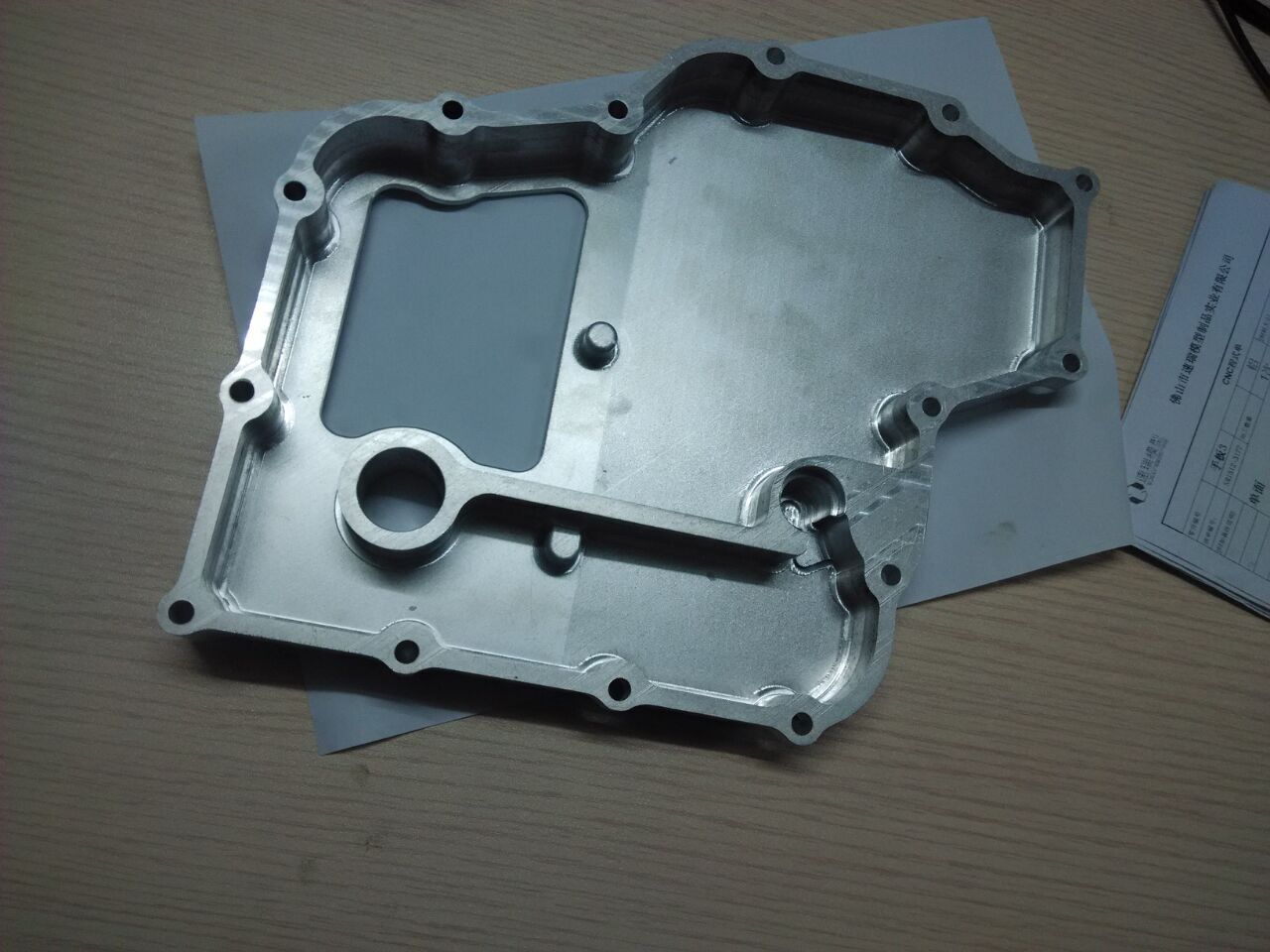
  • Mill the main level as appeared in china precision machining oem parts.
  • Stop the shaft.
  • Remove the square, pivot it 90 degrees, and remount it in the tight clamp against the workstop.
  • Mill the subsequent level as appeared in china high-precision tooling suppliers.
  • Repeat the cycle for the excess two pads.
  • Stop the shaft and measure the distance across the pads.
  • Adjust profundity with the knee varying to plant to the ideal size.
  • Remember that cut profundity will be one portion of the absolute size distinction. For instance, if the distance across the pads is 0.020″ over the ideal size, machine an extra 0.010″ from every level.

A hexagon can be machined utilizing a hexagon collet block by following similar advances.

An ordering apparatus has a shaft that can be turned physically and afterward secured wanted positions. Situating the workpiece in this kind of apparatus is called direct ordering. An ordering installation regularly utilizes a three-jaw throw or a collet to make sure about the workpiece. Most can be mounted on a level plane or vertically. custom cnc machined precision machining titanium parts suppliers shows a collet type ordering installation. The ordering installation has a ring with certain number of indents around its perimeter. Regular quantities of notchesare 18, 24, 30, and 36. A few models can change the ordering ring, while others don’t. The ordering ring is picked dependent on the number of divisions should be machined on the workpiece. These divisions are dictated by number of highlights to be machined.

This article is from http://www.tinymachining.com/

Rotational Table Setup

Revolving TABLE

The revolving table comprises of a substantial base on which a round worktable is mounted. Numerous rotating tables can be mounted either evenly or vertically. The table contains T-spaces for mounting work and is associated with the base by heading that permit it to be turned easily and precisely. The table has degree graduations around its outskirts to help in situating. A hand wheel associated with a stuff set is utilized to pivot the table. Since the stuff set produces gear decrease, the hand wheel should be pivoted a few times to make one upheaval of the table.

This stuff decrease builds precision and control when situating the table. The turning table might be secured position to keep it from floating during arrangement or machining. Numerous rotational tables have a middle opening right through the work table, and some have a Morse tighten inside this opening for mounting tighten shank work-holding gadgets. chinese mold component machining suppliers shows a turning table.

Rotational Table Setup

Most revolving table tasks include mounting the rotational table evenly. It should be mounted to the processing machine table in a similar way as a processing tight clamp. Typically the factory tight clamp should be taken out to make enough space. Ensure that the factory table and turning table base are both liberated from burrs and garbage. The rotating table can typically be attached to the factory table utilizing the T-openings and a similar equipment utilized for the tight clamp.

Subsequent to mounting the revolving table on the plant table, the following stage is to adjust the turning table focus line to the machine shaft focus line. This arrangement can be accomplished in china 4 axis cnc machining manufacturers by moving the processing machine pivot hand wheels.

  • A 0.0005″ graduated dial test pointer should be mounted in the shaft in a throw or collet so it can pivot alongside the axle.
  • The opening in the turning table should be definitely lined up with the axle centerline. To do this, place the machine shaft in impartial and the pointer right over the highest point of the turning table opening.

Pivot the shaft by hand one full turn. While turning the axle, watch where the pointer contact ball is in relationship to the middle opening. Change the processing machine table outwardly until the pointer contact ball gives off an impression of being pivoting concentrically with the opening in the table. This strategy is simply expected to get the table arrangement close so as to get the china precision machining oem parts.

  • After outwardly adjusting the shaft and rotational table, the marker can be let down into the opening. At that point position the pointer contact against the outside of the opening to preload the marker and zero the dial face. Next, pivot the axle again by hand. Note the pointer dial perusing. Perform changes as though playing out any pointer clearing arrangement (shrouded in best precision micro cnc machining, brass small parts). Focus the shaft and revolving table inside 0.0005 “
  • When arrangement has been accomplished, lock the X-and Y-tomahawks and set the micrometer collars to zero or potentially set the DRO to zero. This article is from http://www.tinymachining.com

Settle the Axle

Ram

The ram permits the whole head to be pushed ahead and in reverse and afterward secured position during steel cnc machining parts china. This development is given to build the workpiece limit of the machine. The lower part of the slam contains a dovetail that is fitted to a mating dovetail space in the highest point of the turret.

The dovetail guarantees that the head moves to and fro precisely in an orderly fashion and promises high precision machining efficiency. The slam additionally contains a rack and pinion gear framework. Turning the smash changing switch or nut pushes the slam ahead or in reverse. To move the smash, first slacken the clasping jolts, at that point pivot the changing switch. When in position, re-tighten the clasps.

Similarly as with the turret, consistently be certain the smash clasping jolts are fixed prior to starting any machining activity, or genuine injury can result. The smash should never be moved as a machine slide during machining activities.

HEAD

The top of the vertical factory contains the instruments for holding and driving cutting apparatuses. Its fundamental development and parts are like the top of a drill press however with added highlights. Figure 6.1.12 shows an average vertical processing machine head and marks its parts.

Shaft

The axle is an unequivocally ground shaft. An opening goes through its center to oblige different cutting-instrument holding gadgets and the drawbar. The strung drawbar goes through the shaft from the highest point of the head. These strings give a methods for making sure about instruments, for example, drill tosses and collets to the axle. The highest point of the drawbar contains a hex for fixing the drawbar into the toolholding gadget with a wrench. Within measurement of the lower end of the shaft is tightened for precisely focusing toolholding gadgets in the axle.

Most current vertical processing machines use a standard shape known as a R-8 shape. A little key inside the axle goes about as an approach to both adjust toolholding gadgets inside the shaft and help in driving them. Precision machined parts factory shows the fundamental pieces of the shaft.

Setting Spindle Speed

An engine on top of the head pivots the axle. Most vertical plants have a high/neutalllow range switch that controls a little transmission gear train inside the head. This switch ought to be put in the reach that compares with the ideal RPM. Most When physically changing belt positions on a machine: with step cone pulleys, turn off the fundamental capacity to the vertical factory. Never endeavor to change these belt positions with the axle pivoting.

Current china 4 axis cnc machining manufacturers are furnished with a variable-speed belt drive. To set the RPM on this kind of plant, first select the ideal reach (high or low) and turn on the shaft. At that point a dial situated on the facade of the head is pivoted until the ideal RPM is reached. Remember that the variable speed change dial possibly be turned when the machine is running.

Axle Brake

The axle brake switch can be somewhat turned forward or back to rapidly stop the shaft. It can likewise be pulled out to secure the axle. It is imperative to make sure to deliver the lock prior to beginning the shaft to evade unnecessary wear on the axle brake system. This brake will possibly work when the shaft is in low or high reach, not when in impartial. china custom high precision aluminum cnc parts shows the utilization of the axle brake.

This article is from http://www.tinymachining.com