Klarm Machining Promotes CNC Milling Machining

Custom Fixtures

At the point when a section has an exceptional shape and needs exact area alongside a profoundly secure clasping framework, a custom installation can be utilized. An installation is a specially fabricated workholding gadget explicitly intended to oblige a particular part. This technique can be extremely valuable for protecting parts with abnormal shapes and permits reliable referring to from basic dimensional surfaces.

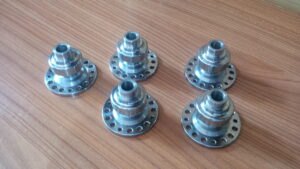
Installations are normally costly because of their absolutely custom nature, which requires a lot arranging, plan, custom machining, and numerous materials. Custom installations are generally braced straightforwardly to a machine table, bed, or gravestone. China precision machining services suppliers shows a custom apparatus.

Cycle PLANNING

Normal CNC processing activities incorporate face and fringe processing, opening, taking, two-dimensional shaping, three-dimensional surfacing, and holemaking. Every one of these individual undertakings is alluded to as an activity. The mix of all tasks needed to machine a section is known as an assembling interaction.

Before programming or setting up apparatuses and the machine, the designing drawing should be firmly analyzed and the creation of the part should be arranged beginning to end. The arranging of workholding gadgets, tooling, and the request for machining activities rely upon the part’s highlights, resiliences, and required surface completions determined by the drawing. When an intensive system has been resolved to deliver a section, the means are then definite on an archive called a cycle plan. This arrangement will incorporate a portrayal of every activity, the apparatuses required, speed and feed information, workholding data, different notes and remarks, and frequently a sketch portraying the part direction. This report is significant not just for the underlying programming of the part, yet additionally as a kind of perspective for any arrangement individual or administrator who will machine the part later on.

There is no normalized design for composing a CNC program that is viable with all machine control brands and models. Each machine control producer has built up its own interesting programming design.

Every one has minor contrasts, yet the standards of a program are something very similar among them all. The programming models all through this unit will relate the most near Fanuc-type and Haas regulators. Be that as it may, the standards might be applied to any producer’s organization (see each machine’s modifying manual).

Recollect from the CNC presentation unit that G90 sets supreme situating and G20 sets inch units. Presently the G17 has been added to set the XY plane, or the standard arrange framework direction. All programming models in this unit will be in outright mode and on the XY plane.

This article is from http://www.tinymachining.com
Rapid Traverse

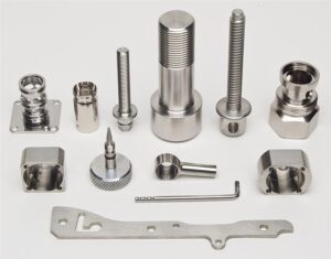
Fast navigate developments should be performed cautiously in a CNC going machine to forestall crashes. Uncommon consideration should be paid to the shifting lengths of the cutting apparatuses and that they are so near other machine parts and the workpiece. Another thought is the area of the device before and toward the fruition of the fast developments. For example, if the instrument is an ID working apparatus, be certain it is withdrawn from the ID of the part preceding making a quick movement in the X-pivot or moving to a device change position. As an instrument moves toward the work, likewise be certain that there is a lot of leeway to forestall an impact. The cutting apparatus ought to never contact the workpiece during a quick navigate development.

Direct interjection synchronizes the movement of (at least one) tomahawks to move the instrument in an orderly fashion. For china precision machining parts suppliers to create a straight line, the machine should begin moving every hub at exactly a similar time, move them at the proper feed rate, and quit moving the two tomahawks at the objective simultaneously.

To move the apparatus in a direct way on a turning place, a G1 is told alongside the directions for the end position of the development. A feed rate should likewise go with the recently customized position. Machine feed rates are communicated in the G1 block with a F-character followed by a feed esteem. A feed rate order is modular and in the event that one isn’t customized in a square, at that point the last modified rate stays dynamic.

Feed rates for CNC turning can be in either inches every moment (IPM) or inches per upset (IPR). IPR is more normal for turning. A modular G-code should be modified to set the machine control to the proposed units. On numerous machines a G98 is utilized for IPM and G99 is utilized for IPR. It is a decent practice to incorporate the ideal setting for the feed rate units toward the start of the program in the protected beginning square. cnc machining turning parts manufacturers shows an illustration of a basic direct movement between two focuses and the comparing program code.

Roundabout Interpolation for Turning- – G2 and G3

CNC turning focuses can likewise make round movements (called bends) with the device tip for machining fillets and radi. To program a curve, the instrument should initially be situated toward the beginning point where that circular segment starts. Once there, a G-code is given to demonstrate whether the curve heading is clockwise or counterclockwise. On the off chance that the curve turns clockwise from begin to end, a G2 code is utilized. On the off chance that the bend turns counterclockwise, a G3 is utilized. On most turning habitats the cutting device is on the rear of the workpiece and a G2 will make a sunken range and a G3 will make a raised sweep (corner round).

cnc precision machining factory shows a marked illustration of the significant pieces of a circular segment. It is imperative to get comfortable with every one of these parts prior to programming. Preceding cutting the bend, the cutting instrument should be situated at the curve’s beginning stage with a standard G1 or GO. After the device is in position, the code for the curve course is given and the software engineer should recognize the end point where the bend stops (recollect that the instrument is now starting toward the beginning point). Data about the circular segment’s size should be given in a similar square of code. There are two strategies for programming the size of the circular segment: programming a span esteem and recognizing the bend’s middle point area.

This article is from http://www.tinymachining.com/