Klarm Machining, good choice for your CNC Program

M-codes are additionally used to turn coolant on and off in the machine. Coolant is typically turned on when the device rapids to the freedom plane and is normally killed toward the finish of a machining activity in china precision cnc titanium machining before an instrument change. The accompanying three coolant orders are normal:

M7 Mist coolant on

M8 Flood coolant on

M9 C oolant off

Not all machines will have the decision of fog or flood. They may just have one, so select the appropriate code for the given machine coolant framework type.

Numerous machines don’t permit a coolant code and a shaft code to be told together, since two M-codes are typically not permitted on a similar square.

A few machines get around this by permitting a M13 or a M114 code to both beginning the axle and turn the coolant on. This code doesn’t pick among flood and fog and will for the most part turn on the machine’s default coolant framework. Once more, check the machine’s manual to figure out which codes apply. In the event that a machine doesn’t acknowledge M13/M14, a different M7 or M8 order is typically customized in the square previously or after the shaft start. The coolant/shaft blend codes are:

M13 Spindle on clockwise with coolant

M14 Spindle on counterclockwise with coolant

Succession Numbers

Grouping numbers can be put toward the start of squares of code to fill in as a mark. They can be utilized for each square or irregularly all through the program to fill in as markers that help discover explicit segments of the program. Each arrangement number starts with an “N” character and they should increment through the program (e.g.. N2, N4, N6, N8, and so on; N5, N10, N15, N20; and so forth) The augmentations between numbers don’t make any difference on most machines as long as they are in expanding request. Numerous developers like to leave mathematical holes (N5, N10, N15, N20, and so on rather than N1, N2, N3, N4, and so on) so extra squares might be embedded if the program is altered later. Succession numbers are discretionary on most present day machines for standard tasks yet might be needed for certain high level activities. The program models in this unit wo exclude grouping numbers.

Finishing a Program in the Correct Format

After the program has been appropriately begun, various sorts of machining activities can be utilized to eliminate material from the workpiece. After all the material evacuation activities are done, the program will require a closure . That finishing initially withdraws the slicing apparatus to the leeway plane and turns off the coolant. Then, the shaft is paused and all machine tomahawks are moved to the machine home situations as when playing out an instrument change.

At that point one last square is required that contains just a M30 code. The M30 order closes the program and resets the program to its start. The program finishing squares may resemble this:

GO Z.1 (CLEAR PART IN Z);

M9 (COOLANT OFF);

G91 G28 Z0. M5 (RAPID TO MACHINE Z-HOME

Furthermore, SPINDLE OFF);

G91 G28 X0. YO. (Quick TO MACHINE XY-HOME);

M30 (END PROGRAM);

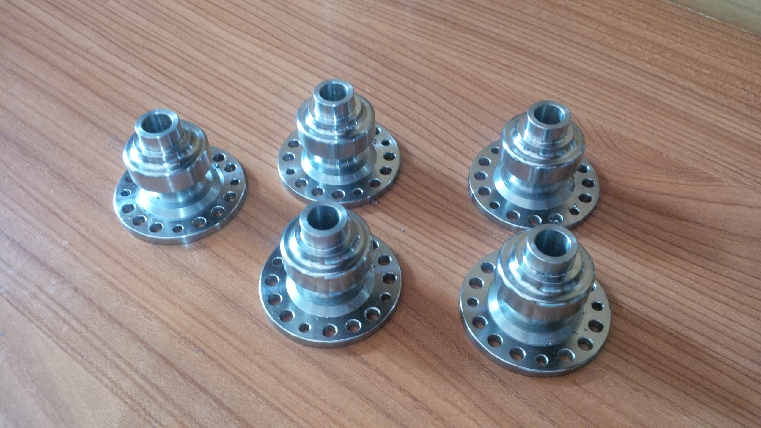
cnc machining metal parts suppliers china shows an illustration of a total program design for most Fanuc or Haas processing machines. This incorporates the program start data and program finishing data. Machining activities for material evacuation will be customized in the middle of the beginning and end and these tasks will be clarified all through the remainder of the unit. Survey china cnc stainless steel turning service manufacturers to see where all the data talked about so far finds a way into the CNC program.

This article is from http://www.tinymachining.com/

Rapid Traverse

Fast navigate developments should be performed cautiously in a CNC going machine to forestall crashes. Uncommon consideration should be paid to the shifting lengths of the cutting apparatuses and that they are so near other machine parts and the workpiece. Another thought is the area of the device before and toward the fruition of the fast developments. For example, if the instrument is an ID working apparatus, be certain it is withdrawn from the ID of the part preceding making a quick movement in the X-pivot or moving to a device change position. As an instrument moves toward the work, likewise be certain that there is a lot of leeway to forestall an impact. The cutting apparatus ought to never contact the workpiece during a quick navigate development.

Direct interjection synchronizes the movement of (at least one) tomahawks to move the instrument in an orderly fashion. For china precision machining parts suppliers to create a straight line, the machine should begin moving every hub at exactly a similar time, move them at the proper feed rate, and quit moving the two tomahawks at the objective simultaneously.

To move the apparatus in a direct way on a turning place, a G1 is told alongside the directions for the end position of the development. A feed rate should likewise go with the recently customized position. Machine feed rates are communicated in the G1 block with a F-character followed by a feed esteem. A feed rate order is modular and in the event that one isn’t customized in a square, at that point the last modified rate stays dynamic.

Feed rates for CNC turning can be in either inches every moment (IPM) or inches per upset (IPR). IPR is more normal for turning. A modular G-code should be modified to set the machine control to the proposed units. On numerous machines a G98 is utilized for IPM and G99 is utilized for IPR. It is a decent practice to incorporate the ideal setting for the feed rate units toward the start of the program in the protected beginning square. cnc machining turning parts manufacturers shows an illustration of a basic direct movement between two focuses and the comparing program code.

Roundabout Interpolation for Turning- – G2 and G3

CNC turning focuses can likewise make round movements (called bends) with the device tip for machining fillets and radi. To program a curve, the instrument should initially be situated toward the beginning point where that circular segment starts. Once there, a G-code is given to demonstrate whether the curve heading is clockwise or counterclockwise. On the off chance that the curve turns clockwise from begin to end, a G2 code is utilized. On the off chance that the bend turns counterclockwise, a G3 is utilized. On most turning habitats the cutting device is on the rear of the workpiece and a G2 will make a sunken range and a G3 will make a raised sweep (corner round).

cnc precision machining factory shows a marked illustration of the significant pieces of a circular segment. It is imperative to get comfortable with every one of these parts prior to programming. Preceding cutting the bend, the cutting instrument should be situated at the curve’s beginning stage with a standard G1 or GO. After the device is in position, the code for the curve course is given and the software engineer should recognize the end point where the bend stops (recollect that the instrument is now starting toward the beginning point). Data about the circular segment’s size should be given in a similar square of code. There are two strategies for programming the size of the circular segment: programming a span esteem and recognizing the bend’s middle point area.

This article is from http://www.tinymachining.com/

Basic Requirement about Tiny Machining Measurement

Tiny machining measurement has strict precision requirements for the precision machined parts. Accuracy measurement apparatuses are fragile and costly. Extraordinary consideration must be taken during use and capacity. Dropping exactness instruments will enormously influence their precision and will much of the time harm them destroyed. Indeed, even little, apparently innocuous knocks can make them not work appropriately. Keep exactness devices from residue, coarseness, and moving machine parts during use. It is acceptable practice to store accuracy instruments from residue, soil, and dampness and to store them with the goal that they don’t contact different apparatuses. When given, use cases in which to store exactness instruments and keep them clean and appropriately greased up to forestall rust and to keep them in smooth working request. This is the very basic requirement for custom precision cnc machining plastic parts china. Accuracy devices approached with deference and care will give a lifetime of solid help, while one snapshot of heedlessness or abuse can rapidly take their lives. When utilizing exactness estimating instruments, additionally remember a few factors that can influence precision. Both the estimating instrument and the part surfaces to be estimated must be spotless of flotsam and jetsam and liberated from any harsh edges.

Since measurement is generally performed inside .001″, things, for example, a hair or little metal or earth particles can influence the precision of the measurement. Continuously wipe the part surfaces and the apparatus estimating surfaces with fingers to expel any sort of flotsam and jetsam that can influence measurement results. This should be kept in mind all the time for precision machining made in china.


Another factor that can affect measurement is temperature. It influences greatly for those precision machined parts which need heat treatment. At the point when metals are machined, heat is frequently made. Warmth makes metals grow, so an measurement taken when part temperature is raised can be not the same as an measurement taken at room temperature. For instance, assume room temperature is 70°F. In the event that a 5″ width bit of aluminum is 100°F following machining, that is 30°F higher than room temperature. That temperature can build the part size by practically 0.002″. The measurement taken at that raised temperature might be inside resilience, yet in the wake of cooling to room temperature, its size change may make it be outside of the resistance. Continuously permit machined parts to cool to room temperature before estimating them with accuracy estimating devices.


Ensuring that accuracy measurement devices are working accurately before use is additionally significant. This is critical for quality precision machined electronics components. Alignment is the way toward checking the exactness of an estimating instrument with another apparatus having a further extent of exactness that is known to be appropriately working and precise, and making changes if necessary. Numerous organizations and schools have alignment designs that require intermittent adjustment of estimating apparatuses. That arrangement can list the devices, the strategies for adjustment, and time spans between alignments. A few organizations and schools will play out this alignment on location, while others may host a third get-together play out this administration. Littler apparatuses are Usually sent to that outsider for adjustment, yet exceptionally huge ones may require an on location visit. In the event that an outsider is utilized, they will give an of the aftereffect of the alignment check, including whether it meets the necessary degree of exactness. An archived adjustment plan might be a necessity if an organization is machining/producing parts for specific ventures, for example, car, aviation, and clinical. Indeed, even with an alignment plan, it is a smart thought to make a couple of short strides before each utilization of an apparatus to check adjustment or confirm that an estimating device is giving right measurements. A portion of these will be examined as this unit proceeds. In the event that a device has been dropped or liable to utilize that may have caused harm, it ought to be recalibrated.


This article is from http://www.tinymachining.com/.