Klarm Machining Offers precision machining services china

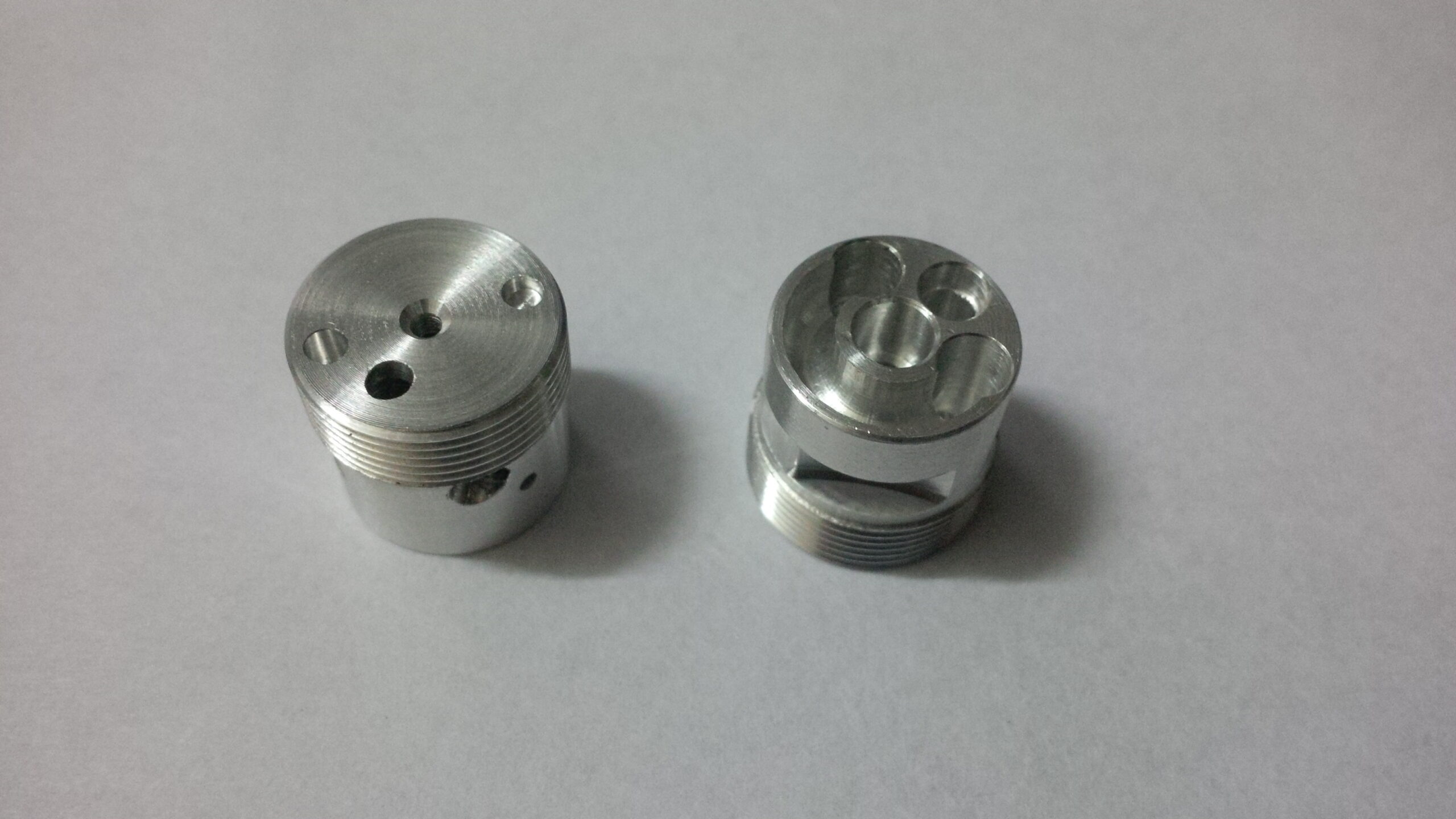
CNC shell-plant and face-factory holders are basic arbors utilized for mounting shell factories and face factories. The arbor comprises of a round pilot distance across for precisely finding the focal point of the mounted instrument and two contradicting drive keys to forestall rotational slippage on the arbor. Cutters slip over the pilot and the drive keys with no power and the instrument is caught and attached by a fastener or cap screw. CNC machining products manufacturers china shows a face-plant toolholder for use in a CNC machining focus.

CNC Tapping Toolholders

There are a few varieties of CNC toolholders utilized for mounting taps. Some hold taps unbendingly in the holder. Others hold taps in particular spring-stacked gadgets that permit expansion and pressure. These are regularly called coasting holders. The machine’s ability for tapping figures out which kind of holder ought to be utilized by cnc precision machining company.

Taps can be held unbendingly with collet throws utilizing ER tap collets fabricated with an inward square that keeps the tap from turning inside the collet. Another technique for tap holding utilizes a spring-stacked brisk change connector to hold the tap. The connector would then be able to be mounted in an uncommonly planned gliding or inflexible tapping throw.

Workholding

CNC hardware and tooling are incredibly costly speculations, so it is reasonable that the additional time a machine spends really machining the item, the more productive the venture is. Workholding gadgets and strategies for machining focuses are consistently advancing and improving so that less time is invested stacking workpieces and more energy is spent machining.

Workholding gadgets for processing can go from basic clips and machine tight clamps to detailed and costly bed frameworks, headstones, and custom apparatuses.

Clips

Clips are a general strategy for connecting workpieces to a machine’s table. Similar styles utilized for manual processing can be utilized for CNC processing also. One kind of clasping framework is the progression block style that permits a stud or jolt to be moored to the machine table T-space and a lash to be drawn down onto a section’s surface to tie down it to the table. Toe cinches permit a section to be hung on its edges by utilizing exceptional serrated jaws to hold into the material and pull the work down close against the table.

Another variety is switch type cinches, which have a helpful snappy delivery switch that utilizes a cam activity component to give clipping pressure. China precision tooling manufacturer shows instances of these clip types.

Clasps are ideal for holding very huge or strangely molded workpieces, or creation work where a tight clamp isn’t reasonable and the volume of work doesn’t legitimize the cost of specially assembled apparatuses. Shockingly, holding work with braces gives no precise strategy to continued situating from one section to another. Each recently stacked workpiece may should be adjusted utilizing a dial pointer, at that point a reference area set utilizing an edge locater. Braces additionally require uncommon programming and administrator consideration since they as a rule reach out over the highest point of the workpiece surface, making the potential for crashes high. Figure 8.5.21 shows an enormous workpiece got to the table of a machining focus with step clasps.

This article is from http://www.tinymachining.com

CNC Precision Machining Company Setting a Work

The workpiece arrangement technique builds up a work counterbalance or beginning area for the WCS. AIll workpiece arranges for programming will be referred to from this beginning. This is set up by finding the work counterbalance or “move” from the MCS starting point to the proposed WCS birthplace.

Review that the MCS never changes position. It is referred to at a similar position each time the machine is homed. Consider this point a perpetual reference point. Since the situation of this machine starting point never shows signs of change, yet the work cause changes with each new workpiece arrangement, the work balance for the part is characterized as a distance referred to from the MCS root. A few controls consider this counterbalance a workshift in light of the fact that it basically moves the machine inception to the area of the work beginning (or the other way around relying upon the machine). Carbon fiber cnc service factory shows an illustration portraying work counterbalance.

On turning machines, the workpiece will change long and position from one occupation to another and requires the cause to be reset in the Z-pivot for each new position. Notwithstanding, the middle line of the workpiece and the middle line of the axle hub are constantly adjusted, so the cause for the X-pivot stays as before from one occupation to another.

There are numerous varieties in the manner every maker’s machine is set up. The standards in the models portrayed next ought to apply to all machine controls.

Fundamental strides for setting a work balance:

  • The workpiece is introduced in the machine.
  • The turret is ordered to a confronting apparatus by utilizing the device change order.
  • The Z-hub is run to bring the confronting instrument close to the furthest limit of the workpiece.
  • The axle is begun utilizing the legitimate M3 or M4 code in MDI mode.
  • The part is looked by running a confronting device across the work utilizing the handwheel until the face is tidied up (no surface left un-machined).
  • The turret is run to a protected position and filed to a vacant position.
  • A gage block is held against the essence of the part.
  • The face of the turret is gradually and painstakingly ran against the gage block until a slight drag is felt. The length of the square is the separation from the planned part beginning to the essence of the turret (the reference point).
  • This gage block length is deducted from the current MCS Z-pivot position.
  • The coming about esteem addresses the separation from the MCS beginning to the WCS source for the Z-hub and is gone into the work balance page in the MCU.

The china cnc machining process supplier shows an illustration portraying the part, gage square, and turret being utilized to set a work balance.

It is a common misinterpretation that the drawtube string commitment affects cinching pressure. The drawtube just sets the size range among open and shut position. Eventually, the grasping pressing factor is resolved exclusively by the machine’s air or pressure driven controller for the collet/hurl nearer framework.

Some turning MCUs such as precision stainless steel cnc turned parts manufacturers utilize a less complex technique, and as opposed to deciding a genuine distance, they simply require a “set Z” catch to be squeezed. The MCU consequently plays out the computation and stores the right an incentive on the work counterbalance page.