Some cool gear grinding photos:
Doorwerth NL – Kasteel Doorwerth 05
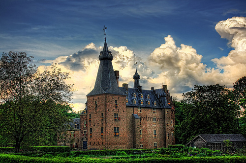
Image by Daniel Mennerich
The original castle, almost certainly wooden, is initial described in 1260 when it was besieged and burned to the ground, soon after which it was rebuilt in stone. In 1280 this second castle was once more besieged and this time the bailey was burned down. This castle probably consisted of a straightforward hall-maintain, two stories higher with 1.20 meter thick walls, and featured a surrounding moat which was fed by the nearby river Rhine.
During the 14th century the castle was continually enlarged. Doorwerth Castle was initially the property of the Van Dorenweerd loved ones. In 1402 Robert van Dorenweerd committed the castle to the Count of Gelre, Reinald IV. In return Robert was granted the castle and its land in fief. About the middle of the 15th century the castle was enlarged again, this time by knight Reinald van Homoet, the 10th Lord of Dorenweerd, who was also the owner of Doornenburg Castle.
Doorwerth Castle reached its largest kind just following the middle of the 16th century below Daem Schellart van Obbendorf, the 15th Lord of Dorenweerd. He made the castle and the group of buildings on the bailey into a unity and adjusted them for far more space and comfort. By 1560 Doorwerth Castle had almost reached its present appearance. About 1637 the bailey was rebuilt to its present look and a dike was built around the castle to protect it from flooding of the river Rhine.
Shortly soon after, the castle changed ownership due to monetary troubles and was granted in fief to a German Count, Anton I van Aldenburg. His successors did not alter the castle or bailey but did acquire far more land. At the finish of the 18th century the castle was no longer inhabited, but was looked soon after by a steward for its owners who now lived in England.
Image from web page 463 of “Farm machinery and farm motors” (1908)
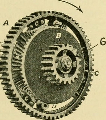
Image by Net Archive Book Images
Identifier: farmmachineryfar00davi
Title: Farm machinery and farm motors
Year: 1908 (1900s)
Authors: Davidson, Jay Brownlee Chase, Leon Wilson
Subjects: Agricultural machinery
Publisher: New York, O. Judd firm [etc., and so on.]
Contributing Library: The Library of Congress
Digitizing Sponsor: Sloan Foundation
View Book Web page: Book Viewer
About This Book: Catalog Entry
View All Images: All Images From Book
Click right here to view book on the internet to see this illustration in context in a browseable on the internet version of this book.
Text Appearing Ahead of Image:
turn will propel the drivewheels. But if the drivewheel attached to pinion Ghappens to travel more quickly thanthat attached to shaft F the^^^^. , pinion C will revolve and ^9^^EB^^^£.^^SJliL ^^^^^ ^^^ pinion A will propel^^^^S»^BSi^rtF«»c the gearing. Usually there are some very severe jerks onthe transmission gearing ofan engine and some com-panies are now inserting intheir compensating gears aset of springs which take this jar off the gearing. 590. Traction.—Any traction engine has energy enoughto propel itself more than the road and through the fields pro-vided the drive wheels do not slip. Consequently thematter of the wheels adhering to the ground is an im-portant part. Exactly where the road surface is firm there is nodifficulty but in a soft field fantastic problems is experienceddue to the truth that the lugs of the drive wheels tear upthe earth and enable the drive wheels to move withoutmoving the engine. It is a typical belief that the driv^ewheel which has the sharpest lug is the one particular which will
Text Appearing Soon after Image:
FIG- 335—COMPENSATING GEARS 452 FARM MOTORS adhere to the ground the very best. In nearly all instances thisis not accurate, since the lug which is sharp is really apt to cutthrough the earth, whilst a single which is dull or round anddoes not have such penetrating effect will pack the earthdown and thus make far more resistance for itself whilepassing via the earth. Nearly every single engine builderhas a style of lug of his own. Fig. 338 shows a newstyle of traction wheel which appears to be providing verygood results. The more weight that can be put on tothe drive wheels of an engine the much better it will adhereto the ground, providing the surface is firm enough tosupport the load. This makes the matter of location of the major axles upon theboiler an essential element.When the boiler is rear-mounted it is clear thatmore of the weight isthrown upon the frontwheels, which act as aguide, than when thePjg ^,g boiler is side-mounted. Therefore one would be led tobelieve that the side-mounted traction engine will havebetter
Note About Images
Please note that these pictures are extracted from scanned web page photos that may have been digitally enhanced for readability – coloration and appearance of these illustrations may not completely resemble the original function.