A few nice wire cutting photos I discovered:
Image from page 33 of “Valve setting: simple methods of setting the plain slide valve. Meyer reduce-off. Corliss. and poppet varieties” (1908)
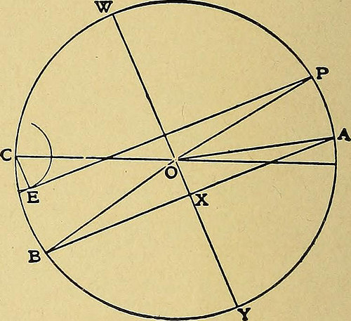
Image by Web Archive Book Images
Identifier: valvesettingsimp00coll
Title: Valve setting: basic methods of setting the plain slide valve. Meyer cut-off. Corliss. and poppet kinds
Year: 1908 (1900s)
Authors: Collins, Hubert Edwin, 1872-
Subjects: Steam-engines
Publisher: New York [etc.] Hill publishing organization
View Book Page: Book Viewer
About This Book: Catalog Entry
View All Pictures: All Images From Book
Click right here to view book on the web to see this illustration in context in a browseable on-line version of this book.
Text Appearing Before Image:
Text Appearing Soon after Image:
FIG. 20. FIG. 21. finish the diagram by drawing in the other valve circle and the two lapcircles, and laying off on the crank circle the points corresponding to theother valve movements. Problem V. Offered the cut-off, release, compression, and width ofport. It is assumed that the width of the port is equal to the maximumopening of the exhaust port, and to construct the diagram it will firstbe required to uncover the travel of the valve, which is carried out, as shown inFig. 21, by drawing a circle of indefinite radius and marking on it pointsof cut-off, release, and compression. This can readily be completed, considering that thesepoints, if provided in terms of the stroke, as explained in Chapter III,might be discovered in terms of the angle turned by way of by the crank. Jointhe points of release and compression by the line A—B and via 0draw a diameter perpendicular to this line. It is then plain that theratio of valve travel to the offered width of port is equal to the ratio ofW—Y to X—Y and from this the trav
Note About Images
Please note that these pictures are extracted from scanned web page pictures that might have been digitally enhanced for readability – coloration and appearance of these illustrations may possibly not completely resemble the original operate.
Image from page 9 of “The Parisian tailor system of dress cutting..” (1890)
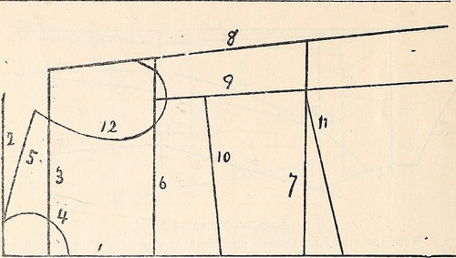
Image by Internet Archive Book Photos
Identifier: parisiantailorsy00levi
Title: The Parisian tailor system of dress cutting..
Year: 1890 (1890s)
Authors: Levis, D. I. [from old catalog]
Subjects:
Publisher: [n.p.]
View Book Web page: Book Viewer
About This Book: Catalog Entry
View All Pictures: All Pictures From Book
Click here to view book on the internet to see this illustration in context in a browseable on the internet version of this book.
Text Appearing Ahead of Image:
square make a dot on line 1 six inches under line 4.Make another 2 inches inside of this dot, and yet another four measuremore than Waist measure, employing back Waist figures, and draw lines12, 13, 14 and 15, as shown in reduce. TRACING FRONT. 1. Lay lining as for Back Trace line 11 from line 1 to 9 up line 9to 12, up 12 lo five, up five to 4, down line four, 26 and 1 down 24 and 15,19, 13, 18, 20, 14, 16, 17, 21 and 22. Get rid of draft, reduce out, allow seams except Neck and Arm Eye.Replace draft for Beneath Arm gore. Trace line 7 from 9 to eight upseam except Arm Eye. 9, 12, down 23 and 25, reduce out let TRACING OUT BACK. 1. Lay lining on a table double and tack drafting on the lining,First trace line four from line 10 to 7 up line 7 to 2, and line 2 to 8down line 8 to ten, down lines ten, 12 and 13, remove draft, reduce out,permitting seams except at Neck and Arm Eye. 2. Replace for side type Trace line four from six to 11 up lines 11, 6 and 9, down lines 14 and15, let seam except Arm Eye. Parisian Tailor Method of Dress Cutting
Text Appearing Right after Image:
DRAFTING FRONT. Lesson No. three. 1. Draw line 1 and 2 as shown in reduce. Make a dot on line two ac-cording to Neck measure, utilizing Front Neck figures. Line 3 is drawni~y2 inches below line 2. 2. With curvatures location the N point at dot on line two and neckmeasure on line 1, draw line 4, location the P point at exact same dot and 7inch mark in the same curve on line three, and draw line five to theShoulder measure. 3. Now make a dot *4 of the Arms Eye measure under the endof line five, and draw line six from line 1, square across this dot to thewidth of front. Line 7 is the Under Arm measure beneath line six andy2 in. a lot more than the width of front from 1. Draw line eight as shownin cut. Place the square corner of square at the junctions of line 6and eight and make a dot at Arms measure, making use of small Arms Eye fig-ure. Make a dot on line 7 in the identical manner, inside line eight. Drawline 9 as shown in cut. Now make a dot on line 9 y? inch belowline six, yet another three inches. Make a dot on line 1 four inches below line6. Make another on line 1 th
Note About Images
Please note that these images are extracted from scanned page pictures that could have been digitally enhanced for readability – coloration and look of these illustrations may not completely resemble the original work.
Image from web page 18 of “Merz’s practical cutting program for ladies’ jackets and cloaks ..” (1911)
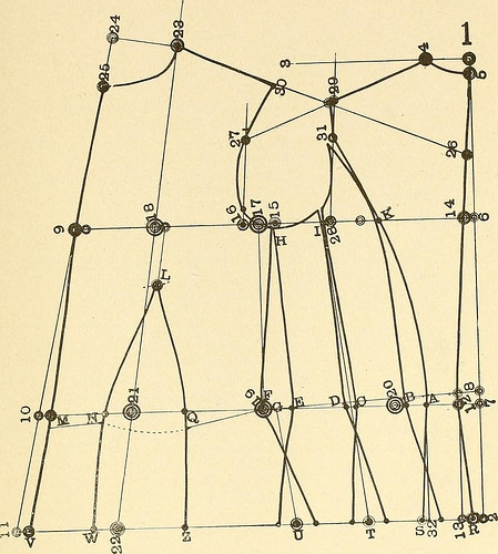
Image by Web Archive Book Pictures
Identifier: merzspracticalcu00merz
Title: Merz’s sensible cutting method for ladies’ jackets and cloaks ..
Year: 1911 (1910s)
Authors: Merz, William. [from old catalog]
Subjects: Tailoring (Women’s) [from old catalog]
Publisher: [New York?] W. Merz
View Book Page: Book Viewer
About This Book: Catalog Entry
View All Pictures: All Photos From Book
Click here to view book online to see this illustration in context in a browseable on the web version of this book.
Text Appearing Before Image:
perpendicidar line from A to 32. From 29to 31 is y^ back depth. Curve the line frnm 31 via K andA to S, which is % inch from 32. Draw the guide lines fromI through the center of C and D to establish T, and from Gto U parallel with ]>revious line. Divide the balance 3^4 inchesin 5 equal parts, which is -J^ inch every, and add a single on eachside of U, a single on each and every side of T, and the fifth -)4 inch on theside of S draw guide lines from B to the side of S from Cand D, from E and F to every side of T, and each side of U.Then draw the front center line from M to V parallel with theoutside line. From V to W is y% inch far more than from M to N.The nieasure from 22 to V is hip surplus four^^ inches on thisdraft and has to be cut out from W to Z. Draw guide linesfrom Q to Z and from N to V. Curve all lines as representedand the draft is prepared to be cut out. The length lines are ex-plained in styles. About the use ()f the cuntri)] measure, seeDiagrams X. and XL For Ladies Jackets and Cloaks. 17
Text Appearing Right after Image:
Diagram III. Merzs Practical Cutting Method Diagram IV.TIGHT^FITTING JACKET. TWO DARTS. All following drafts exactly where no special measures are givenare from the tahle of proportional measures of 36 bust. For two darts the front center line, ten to M and 11 to V,is J4 inch. Pivot at 25 and draw a circular line by means of L toestablish the height of the darts and put the darts, 43 and 44,/12 bust apart on each side of L. From M to N is % waistfrom N to O is V12 bust to be cut out from O to P is ^/^abust from P to O is the balance of the front waist surplus21 to M = two>4 inch on this draft. From V to W is J4 inchmore than from M to N from W to X ^ inch a lot more thanfrom N to O to be cut out from X to Y is 14 inch a lot more thanO to P from Y to Z is the balance of the hip surplus 22 to V= three inches on this draft. Then draw the guide lines from 9 to M from M to Vfrom the first dart point 43 to N from N to W from 43 to O from O to X and from the second dart point 44 to P fromP to Y from 44
Note About Images
Please note that these photos are extracted from scanned page pictures that might have been digitally enhanced for readability – coloration and appearance of these illustrations could not perfectly resemble the original function.