Verify out these internal cylindrical grinding pictures:
Image from web page 365 of “Railway mechanical engineer” (1916)
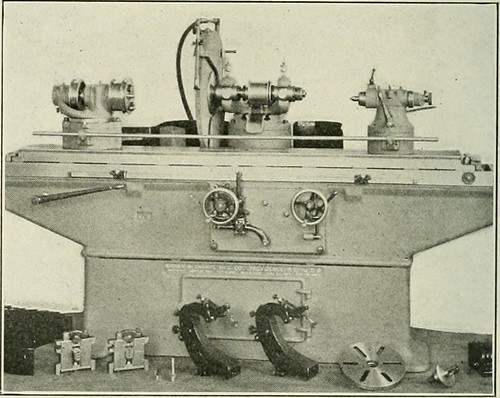
Image by Net Archive Book Images
Identifier: railwaymechanica96newy
Title: Railway mechanical engineer
Year: 1916 (1910s)
Authors:
Subjects: Railroad engineering Engineering Railroads Railroad vehicles
Publisher: New York, N.Y. : Simmons-Boardman Pub. Co
Contributing Library: Carnegie Library of Pittsburgh
Digitizing Sponsor: Lyrasis Members and Sloan Foundation
View Book Page: Book Viewer
About This Book: Catalog Entry
View All Pictures: All Images From Book
Click right here to view book on the web to see this illustration in context in a browseable on-line version of this book.
Text Appearing Before Image:
Typlcai Set-Up for Grinding a Little Pin particular throw-blocks adapt this machine for crankshaft perform.The truth that it is a universal machine enables it to do alarge assortment of function, like straight cylindrical grindingand the grinding of abrupt tapers. With the tool rest, it grinds cutters and reamers, boring bars and other tools. Theadvantages this machine possesses over previous models liein the wider range of perform it will cover. With the internal
Text Appearing After Image:
Brown & Sharpe Universal and Crankshaft Grinding IVIachlne attachment and tool rest illustrated, it is capable of all thework done by previous models and is also adapted to grind-ing all automotive components except cylinders en bloc. The No. 4 grinder has a capacity to deal with function 60 in. June, 1922 RAILWAY MECHANICAL ENGINEER 353 in length with a swing of 20 J4 in. in diameter and 15 yi in.more than the water guards. The wheel spindle has hardened 4 k Arrangement for Internal Grinding bearings ground and lapped, operating in self-alining phos-phor bronze boxes offered with means of compensation forwear. The automatic cross feed will move the wheel from.00025 to .004 in. at every reversal of the table as preferred. It is automatically disengaged when the operate is to size. Thetable travel is automatic, getting controlled by easily adjust-in a position dogs. The speeds and feeds of the wheel and workand table feed are entirely independent of each and every other. Asingle lever begins and stops the rotation of the operate
Note About Photos
Please note that these pictures are extracted from scanned page photos that may possibly have been digitally enhanced for readability – coloration and appearance of these illustrations may possibly not completely resemble the original perform.
Image from web page 365 of “Railway mechanical engineer” (1916)
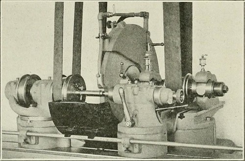
Image by Web Archive Book Pictures
Identifier: railwaymechanica96newy
Title: Railway mechanical engineer
Year: 1916 (1910s)
Authors:
Subjects: Railroad engineering Engineering Railroads Railroad cars
Publisher: New York, N.Y. : Simmons-Boardman Pub. Co
Contributing Library: Carnegie Library of Pittsburgh
Digitizing Sponsor: Lyrasis Members and Sloan Foundation
View Book Page: Book Viewer
About This Book: Catalog Entry
View All Photos: All Pictures From Book
Click right here to view book online to see this illustration in context in a browseable on the web version of this book.
Text Appearing Just before Image:
iction clutches, running in oil with manage handles conveniently positioned 1 at the apron and one at thehead finish of the lathe. The clutches call for no adjustmentat any time and are made to pull a tiny a lot more than theload imposed. In addition, these lathes incorporate other Lehmann characteristics, ^■T^ * ■■ I WSSSUmmm 9 r- ^ -^■^•^-^ • J ,•■> • M L|gj I^R A ^^w^^g ^fii^^i ^ Lehmann Portable Lathe with Compact Motor Drive Arrangement such as the patent quick adjust mechanism, tailstock spindlelocking device, rod and screw shift, etc., which have beendescribed at different times in the Railway MechanicalEngineer. Universal and Crankshaft Grinding Machine ANEW grinder, recognized as the No. 4 universal andcrankshaft grinding machine, has been created bythe Brown & Sharpe Manufacturing Organization, Provi-dence, R. I. It is primarily a universal machine, but adaptedto the grinding of crankshafts. Raising blocks under theheadstock and footstock and a wheel of large diameter, also
Text Appearing After Image:
Typlcai Set-Up for Grinding a Small Pin specific throw-blocks adapt this machine for crankshaft function.The truth that it is a universal machine enables it to do alarge variety of work, including straight cylindrical grindingand the grinding of abrupt tapers. With the tool rest, it grinds cutters and reamers, boring bars and other tools. Theadvantages this machine possesses over previous models liein the wider variety of work it will cover. With the internal
Note About Images
Please note that these images are extracted from scanned web page pictures that may have been digitally enhanced for readability – coloration and appearance of these illustrations could not perfectly resemble the original function.
Image from web page 119 of “American engineer and railroad journal” (1893)
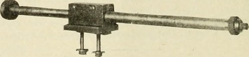
Image by Web Archive Book Images
Identifier: americanengineer79newy
Title: American engineer and railroad journal
Year: 1893 (1890s)
Authors:
Subjects: Railroad engineering Engineering Railroads Railroad automobiles
Publisher: New York : M.N. Forney
Contributing Library: Carnegie Library of Pittsburgh
Digitizing Sponsor: Lyrasis Members and Sloan Foundation
View Book Page: Book Viewer
About This Book: Catalog Entry
View All Pictures: All Pictures From Book
Click here to view book on the web to see this illustration in context in a browseable on-line version of this book.
Text Appearing Ahead of Image:
the shifter. The clutches may be engaged ordisengaged even though the machine Is in motion, thereby allowingperator to drill a hole, remove the drill and substitute atap and tap the hole with no stopping the machine. Thespindle has a swift reverse speed of two to 1. These machines are created in 24, 28, 32, 3ti and 42-in. sizesby the Cincinnati Machine Tool Company of Cincinnati, whomake a st rict i pei ia II j of upright drills. The device consists of a %-in. diameter steel shaft, which isenclosed inside and arranged to revolve inside a steel tubeof 1 in. inside diameter and 40 ins. lengthy. The shaft is sup-ported and provided bearing by bronze bushings pressed into theends of the tube. One end of the shaft carries an emery wheel,which may vary in diameter from 2 ins. upward, according tothe character of the operate essential the other finish carries adriving pulley for a 1 in. belt. The grinder is bolted on the carriage of an ordinary enginelathe, with the axis of the grinding shaft meticulously paralleled
Text Appearing Right after Image:
TirEHMAi Storagi fob Locomotives.—Mr. Druill Halpinssystem of heat storage has been applied to a locomotive boiler of the i hern Railway of England. A cylindrical e tank is placed on top of the boiler, to which it isconnected by indicates of a pipe The r.-eit water, heated to theemperature as thai of the boiler, is passed by means of thisr Below, I he heal ii am taken from the boiler when the engim anding or the afetj valves are Mowing, in this waj a huge supplj of heat is accessible tohelp the boiler when running. In stationary practice a testby Professor Unvvin has shown a coal saving of 19 per cent.with this program. INTERNAL SURFACE GRINDER FOR NARY LATHE. to the center line of the lathe, by implies of the clamp-blockshown in the engraving. The cylinder or tube to be finishedby grinding is set up and centered in the lathe, with a single endin the cnuck and the outer finish supported by a steady rest.The cylinder is rotated gradually by the lathe in one direction of rotation, whilst the emery wheel is
Note About Photos
Please note that these images are extracted from scanned web page pictures that might have been digitally enhanced for readability – coloration and look of these illustrations may not completely resemble the original operate.