Some cool wire cutting services photos:
Image from page 1215 of “Electric railway journal” (1908)
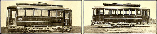
Image by Web Archive Book Photos
Identifier: electricrailway491917newy
Title: Electric railway journal
Year: 1908 (1900s)
Authors:
Subjects: Electric railroads
Publisher: [New York] McGraw Hill Pub. Co
Contributing Library: Smithsonian Libraries
Digitizing Sponsor: Smithsonian Libraries
View Book Page: Book Viewer
About This Book: Catalog Entry
View All Images: All Images From Book
Click here to view book on the web to see this illustration in context in a browseable on-line version of this book.
Text Appearing Before Image:
COUNTY RAILWAY REMODELED Vehicle The interior of the automobile was improved by substitutinglongitudinal seat frames constructed up of angle-iron for theold wood-inclosed frames, with reduction in fire threat.The new arrangement is also much more sanitary, as it iseasier to hold the floor clean. On the side of the vesti-bule opposite to the door a seat for two persons wasbuilt in, and on the door side a folding seat was placed,permitting complete utilization of the vestibule when thedoor is not in use. All of the seats were covered withrattan. With a wish to have a completely sanitary automobile, all ofthe old grooved and reduce moldings were removed andreplaced with plain ones. Incidentally this significantly im-proved the look. Rico sanitary strap hangers,push buttons and buzzers, Consolidated auto heaters andAtchley staffless brakes have been among the devices whichwe added to make the car as worthy of the name safetycar as attainable. Railings were erected on the platformsto separate the operator from the passengers and also
Text Appearing Soon after Image:
LEVIS COUNTY RAILWAY Auto Just before AND Soon after REMODELING 1192 ELECTRIC RAILWAY JOURNAL [Vol. XLIX, No. 26 to serve as a support for the fare boxes. Two verticalrailing posts have been carried clear to the ceiling to serveas guides for the curtains offered to defend the oper-ator from the light behind him. The new arrangementof lamps consists of seven single ones down the centerof the vehicle, 1 in every vestibule, and Golden Glow head-lights, 1 operating at a time. Safety car lightingfixtures have been used throughout. All of the wiring wasinclosed in versatile or pipe conduits. Lastly the carwas offered an desirable interior finish in mahogany,with cream-enameled ceiling and railings. The remodeled cars are in operation along the southshore of the St. Lawrence River opposite Quebec. Theyconnect with the Quebec ferry service, which is on a
Note About Images
Please note that these photos are extracted from scanned page images that might have been digitally enhanced for readability – coloration and appearance of these illustrations may possibly not completely resemble the original work.
Image from web page 392 of “Canadian engineer” (1893)
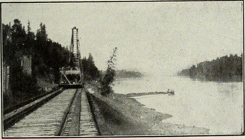
Image by Net Archive Book Pictures
Identifier: canadianengineer22toro
Title: Canadian engineer
Year: 1893 (1890s)
Authors:
Subjects:
Publisher: Toronto, Monetary Instances Print. Co. [and so forth.]
Contributing Library: Engineering – University of Toronto
Digitizing Sponsor: University of Toronto
View Book Web page: Book Viewer
About This Book: Catalog Entry
View All Pictures: All Images From Book
Click right here to view book online to see this illustration in context in a browseable on the web version of this book.
Text Appearing Just before Image:
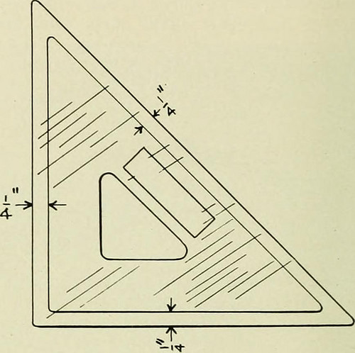
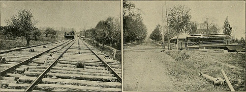
f alternatebents did not fall opposite to a single yet another. The joists have been of dimensions four in. by ten in., beingstaggered and overlapping one particular foot. They were toe-spikedto the cap with six in. wire spikes. The flooring was three in.in thickness. It ought to have been specified as dressed to3 in. thickness, but this was not done, and in consequencethe very first portion of the floor laid was somewhat rough. Thewharf floor was faced with two pieces of 12 in. by 12 in.wealing drift bolted to one particular an additional, as shown in the eleva-tion, and drifted in turn to the caps. This waling was per-fectly lined, and has provided the face of the wharf a veryfinished appearance, and has also completed great service inoperating the wharf to date. Outside of every of the outer bearing piles were drivenspringing piles of fir. These springing piles were drivenrather farther from the bearing piles than is shown on theplan, getting distant three ft. centres at the river bed, and buttedagainst th? u-in. by 14-in. cap with twelve inches clear be-
Text Appearing Soon after Image:
Fraser River, from C.N.P. Railway Track. tween the piles at the leading. Their object is, of course, totake the shock of a vessel coming to her mooring alongsidethe wharf. These springing piles were cut ofT on a bevel,being flush with the upper 12-in. by 12-in. wale on the in-side, and sloping outward at an inclination of 30 to thehorizontal. This uniformity of slope of these outer pilesconsiderably enhances the appearance of the wharft .A.n 8-in.by 12-in. spacing wale was created quick along the whole faceof the wharf, in between these springing piles. Mooring piles had been driven as shown on the- jjlan. 1 ri< ywere braced tD the 4 nearest bearjng piles by means of8-in. by 8-in. struts. On the freight wharf two runways were constructed ac-cording to the specifics shown on the plan. Sliding stringerssupport the removal planks of the flooring more than the run-way, so that when not in use the runways might be coveredin. These sliding stringers operate on rollers suspendedfrom the joists of the adjoini
Note About Images
Please note that these images are extracted from scanned web page images that may possibly have been digitally enhanced for readability – coloration and look of these illustrations may not completely resemble the original work.
Image from page 194 of “North Carolina Christian advocate [serial]” (1894)
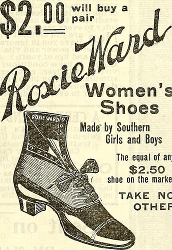
Image by Web Archive Book Pictures
Identifier: northcarolinachr49unit
Title: North Carolina Christian advocate [serial]
Year: 1894 (1890s)
Authors: United Methodist Church (U.S.). North Carolina Conference United Methodist Church (U.S.). Western North Carolina Conference
Subjects: United Methodist Church (U.S.). North Carolina Conference United Methodist Church (U.S.). Western North Carolina Conference Methodist Church
Publisher: Greensboro, N.C., Methodist Board of Publication, [and so forth.]
Contributing Library: Duke Divinity School Library, Duke University
Digitizing Sponsor: Institute of Museum and Library Services, beneath the provisions of the Library Services and Technologies Act, administered by the State Library of North Carolina. Grant issued to Duke University for the Religion in North Carolina project.
View Book Page: Book Viewer
About This Book: Catalog Entry
View All Pictures: All Images From Book
Click here to view book on-line to see this illustration in context in a browseable on the internet version of this book.
Text Appearing Prior to Image:
. Her nose and lip wereraw as beef, with offensive dischargefrom the consuming sore. Physicians ad-vised cutting, but it failed. BloodBalm healed the sores, and Mrs.Guerney is as well as ever. BotanicBlood Balm also cures eczema, itch-ing humors, scabs and scales, bonepains, ulcers, offensive pimples,blood poison, carbuncles, scrofula,risings and bumps on the skin andall blood troubles. Druggists, perlarge bottle. Sample of BotanicBlood Balm cost-free and prepaid bywriting Blood Balm Co., Atlanta,Ga. Describe trouble and specialmedical guidance sent in sealed letter.It is surely worth even though investi-gating such a exceptional remedy asBlood Balm cures the moRt awful,worst and most deep seated blood dis-eases. It Saved His Leg. P. A. Danforth of LaGrange, Ga.,suffered for six months with a fright-ful operating sore on his leg but writesthat Bucklens Arnica Salve whollycured it in 5 days. For Ulcers,Wounds, Piles, its the ideal salve inthe world. Remedy assured. Only25cts. Sold by all druggist.
Text Appearing Right after Image:
WomensShoes Created by SouthernGirls and Boys The equal of any .50 shoe on the industry TAKE NOOTHER Your dealer need to hold the ideal,and the best is ROXIE WARD. GEO. D. WITT SHOE GO. Manufacturers LYNCHBURG, VA. |Wire Railing and Ornamental [ ^WIRE Works./?jiD U F U R CEL CO. No. 311N. Howard St., Baltimore, Md. Manufacture wire railing for cemeter-ies, balconies, &c seives, fenders,cages, sand and eoa) screens, wovenwire, and so forth keo Iron bedsteads.chair*««tt.e«s. &»* C. W. BANNER, M D. OPPOSITE THE MCADOO House. Practice limited to theEye, Ear, Noseand Throat. OFEICE HOURS .—9 a. n>. to 1 p. m. 2:30 p.m.to five p. m. Sunday 9 to ten:30 a m. given«^ thP worthv tinnr. 1p three-tf THOMAS C. HOYLB. N. L. EURE. HOYLE <SL EURE, Attorneys at Law, 119 COURT SQUARE,GREENSBORO, N.O, Special focus given to collections.Loam negotiated. iftnH-1* Mental Strain Impacted Gen-eral Overall health. Medical doctors Doses Weak-ened Stomach. Dr. Miles Nervine CuredMe. Dr. Miles Restorative Nervine brings r
Note About Images
Please note that these images are extracted from scanned page photos that may have been digitally enhanced for readability – coloration and appearance of these illustrations might not completely resemble the original work.
")

")
![Image from page 288 of “Railway master mechanic [microform]” (1895)](https://www.tinymachining.com/blog/wp-content/uploads/2014/08/14761259472_07c8c7f3a3.jpg "Image from page 288 of “Railway master mechanic [microform]” (1895)")