A couple of nice electrical discharge wire cutting images I identified:
Image from page 398 of “The street railway assessment” (1891)
Image by Web Archive Book Images
Identifier: streetrailway03amer
Title: The street railway review
Year: 1891 (1890s)
Authors: American Street Railway Association Street Railway Accountants’ Association of America American Railway, Mechanical, and Electrical Association
Subjects: Street-railroads
Publisher: Chicago : Street Railway Evaluation Pub. Co
Contributing Library: Carnegie Library of Pittsburgh
Digitizing Sponsor: Lyrasis Members and Sloan Foundation
View Book Web page: Book Viewer
About This Book: Catalog Entry
View All Images: All Photos From Book
Click right here to view book on the internet to see this illustration in context in a browseable on the internet version of this book.
Text Appearing Just before Image:
Looking UP THE GRADE. AT THE GREGORY STREET CROSSING. fore built in each and every track, formed of two Z iron beams 8inches deep, set 12^ inches apart, with an I beamextending parallel amongst and as a result forming a doubleconduit in which two groove pulley wheels of 15 inchesdiameter are placed at intervals of 15 feet the I beambeing reduce away on the beneath side where necessary tomake room for the pulleys. The two cables on this outdoors of every single track. A push button in the vehicle strikesa gong in the engineers room, and a set of signals tostop, begin, and so on., enables the vehicles to run by Gregoryavenue when no passengers are to be taken or discharged.This wire is carried on a Y shaped insulated support, inwhich the composition forked ideas are set in glass insula-tors mounted on locust pins, the whole increasing ten inches (^Iaeetlf(ailw!a^ J^A/m/ 373
Text Appearing Following Image:
S. A. COONEY, Constructing Engineer. above the ties. This signal wire is carried among twotrolley wheels, fastened to an arm projecting from thecar. The bigger wheel is 7 inches in diameter, i J^ inches wide with a three^inch groove. Thesmall wheel is ijiinches diameter. Atthe Gregory streetcrossing the signalwire is carried in aconduit getting a i }2inch slot throughwhich the wire israised the exact same asthe cables. The power home, aswill be noticed in theillustration, is a hand-some structure ofstone, with boiler roomin the rear 33 by 33feet, and engine space 60 by 33 feet space is left foradditional engines if required. The baywindow in front is the operating space andoccupies a commanding view of the line.In this room are the levers for controlling allthe machinery, like the air brakes,electric signal from the automobiles and the indica-tor which shows the location of the cars onthe incline. The indicator is also providedwith an automatic electric alarm which ringsa bell to announce the ap
Note About Images
Please note that these photos are extracted from scanned page images that may possibly have been digitally enhanced for readability – coloration and look of these illustrations might not completely resemble the original work.
Image from page 397 of “The street railway evaluation” (1891)
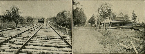
Image by Internet Archive Book Images
Identifier: streetrailway03amer
Title: The street railway assessment
Year: 1891 (1890s)
Authors: American Street Railway Association Street Railway Accountants’ Association of America American Railway, Mechanical, and Electrical Association
Subjects: Street-railroads
Publisher: Chicago : Street Railway Overview Pub. Co
Contributing Library: Carnegie Library of Pittsburgh
Digitizing Sponsor: Lyrasis Members and Sloan Foundation
View Book Web page: Book Viewer
About This Book: Catalog Entry
View All Images: All Images From Book
Click here to view book on the internet to see this illustration in context in a browseable online version of this book.
Text Appearing Just before Image:
Car AT Top OF THE INCLINE. pound T rail. A maximum grade of 14.5 per cent con-tinues for 1550 feet, and about half way up the inclineGregory avenue is crossed on a level. This crossing is quite unusual in the building ofincline planes, and referred to as for special construction, as itwas not permisible to use an open conduit, as vehiclesconstantly cross the line. A narrow conduit was there- THE Reduced TERMINUS. entangled in the moving cable as long as the ropesare exposed. The arrangement is clearly shown in theillustrations. An additional novel device is the provision by which theconductor of every single auto is in continuous communication withthe engineer by indicates of an electric signal wire whichwill be noticed in the illustration as extending along the
Text Appearing Following Image:
Searching UP THE GRADE. AT THE GREGORY STREET CROSSING. fore constructed in every single track, formed of two Z iron beams 8inches deep, set 12^ inches apart, with an I beamextending parallel between and therefore forming a doubleconduit in which two groove pulley wheels of 15 inchesdiameter are placed at intervals of 15 feet the I beambeing cut away on the under side where necessary tomake space for the pulleys. The two cables on this outside of every single track. A push button in the automobile strikesa gong in the engineers space, and a set of signals tostop, start off, etc., enables the automobiles to run by Gregoryavenue when no passengers are to be taken or discharged.This wire is carried on a Y shaped insulated assistance, inwhich the composition forked ideas are set in glass insula-tors mounted on locust pins, the whole rising 10 inches (^Iaeetlf(ailw!a^ J^A/m/ 373
Note About Pictures
Please note that these pictures are extracted from scanned web page pictures that could have been digitally enhanced for readability – coloration and appearance of these illustrations may possibly not perfectly resemble the original work.