Verify out these electrical discharge wire cutting pictures:
Image from page 1003 of “Electric railway journal” (1908)
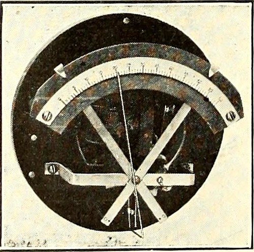
Image by Net Archive Book Pictures
Identifier: electricrailway511918newy
Title: Electric railway journal
Year: 1908 (1900s)
Authors:
Subjects: Electric railroads
Publisher: [New York] McGraw Hill Pub. Co
Contributing Library: Smithsonian Libraries
Digitizing Sponsor: Smithsonian Libraries
View Book Web page: Book Viewer
About This Book: Catalog Entry
View All Pictures: All Photos From Book
Click here to view book online to see this illustration in context in a browseable on the web version of this book.
Text Appearing Prior to Image:
guide inmaking adjustments. The action of the governor is dependent on the Bourdon tube which isconnected to an independ-ent discharge pipe fromthe stress tank. Thefree end of the tube isconnected mechanically tothe indicator needle re-ferred to above. Afterthe governor has been setto the pressure range de-sired, it will automaticallymaintain the stress Pressure GOVERNOR within thoge ,j jt QnWITH CASE REMOVED . * gas or liquid program, thatwill not corrode the Bourdon tube. It can be utilised onboth a.c. and d.c. circuits, and will operate inside set-tings of from 3 to 12 lb. The device is created by the General Electric business,in sizes for rated pressures of 60, one hundred, 160, 300 and500 lb. Governors for higher pressures can also besupplied if desired. Adjustments of the cutting-in andcutting-out pressures are made by moving the pointersshown at the prime of the graduated scale. The case istapped and drilled at the bottom for the pressure pipeand for generating the electrical conduit connections.
Text Appearing After Image:
May 18, 1918 Electric Railway Journal * 975 Trolley Ear Length Is a Factor inWire-Put on Tests Recently Created Show That the Life of theWire Increases Proportionately With theLength of the Ear By G. H. Bolus Designing Engineer, Ohio Brass Organization, Mansfield, Ohio Companies of overhead line material listtrolley ears in all lengths from 7 in. to 15 in.Sales records show that the railway companies of theUnited States and Canada are purchasing a lot more 15-in.ears than those of any other length. The averagerailway man doubtless has standardized on the lengthof ear which he has discovered from knowledge works wellon his line, but it is doubtful whether or not he directly asso-ciates the length of the trolley ear with the put on onthe trolley wire. Some railway properties make a practice of startingtheir installation with a 9-in. ear, operating it untilworn out and replacing with a 12-in. ear to cover upthe worn spots in the wire. The next renewal wouldbe with a 15-in. ear and later renewals would eitherbe m
Note About Photos
Please note that these photos are extracted from scanned page images that could have been digitally enhanced for readability – coloration and appearance of these illustrations may not perfectly resemble the original operate.
Image from web page 372 of “Radiography and radio-therapeutics” (1919)
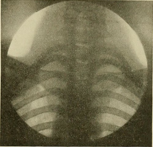
Image by World wide web Archive Book Pictures
Identifier: radiographyradio001knox
Title: Radiography and radio-therapeutics
Year: 1919 (1910s)
Authors: Knox, Robert, 1868-1928
Subjects: Radiography Radiography Radiotherapy
Publisher: New York : Macmillan
Contributing Library: Francis A. Countway Library of Medicine
Digitizing Sponsor: Open Understanding Commons and Harvard Medical School
View Book Web page: Book Viewer
About This Book: Catalog Entry
View All Photos: All Photos From Book
Click right here to view book on the web to see this illustration in context in a browseable on-line version of this book.
Text Appearing Ahead of Image:
is not possible to recordupon a plate. But radiographs which are taken instantaneously are ofgreat value as confirmatory proof of changes in the organs, and shouldalways be taken to full the examination. The importance of havinga thoroughly trustworthy fluorescentscreen have to be borne in mind.It is also essential that the screenbe smooth on the surface, andkept scrupulously clean. Thelead glass protection ought to alsobe kept well polished, for even atrace of dirt or pencil mark on itssurface may lead to difficulty, theimportance of this point beingreadily understood where finedetail is getting dealt with. It is also of importance tohave the patient completely nonetheless,especially when radiography isemployed, because the slightestmovement throughout the exposuremay ruin the worth of a plate. The screening stand need to be connectedto earth by a wire, in order to steer clear of providing the patient a shock fromthe electrical discharges which are given off from the tube and metal fittingswhen the former gets challenging.
Text Appearing Right after Image:
Fig. 247.—Normal reduce cervical and upper dorsalvertebrae. The apical element of both lungs isalso effectively shown. Radiography In radiography of the lungs for diagnostic purposes it is required touse a soft tube in order to obtain the best final results. It is detail in lungs andnot in bone that we appear for. A soft tube of about 3-4 inch spark-gap willallow a massive quantity of current to pass by means of it, and will give extremely gooddetail in the soft parts. Time exposures of any length are of no great worth for diagnosis ifwe are to get plates which will to any extent reproduce what we have seenon the screen, the exposure need to be exceedingly quick in truth, the shortestobtainable is the very best. With a potent modern installation the exposure 284 RADIOGRAPHY could be cut down to T£o of a second. The resulting image is of wonderful worth,because every thing is completely sharp, the heart being represented inoutline by the sharpest possible line. The diaphragm is also sharp, andmay be caught in a stage of
Note About Photos
Please note that these pictures are extracted from scanned web page photos that might have been digitally enhanced for readability – coloration and appearance of these illustrations might not completely resemble the original perform.