Some cool electrical discharge wire cutting pictures:
Image from page 636 of “Electrical globe” (1883)
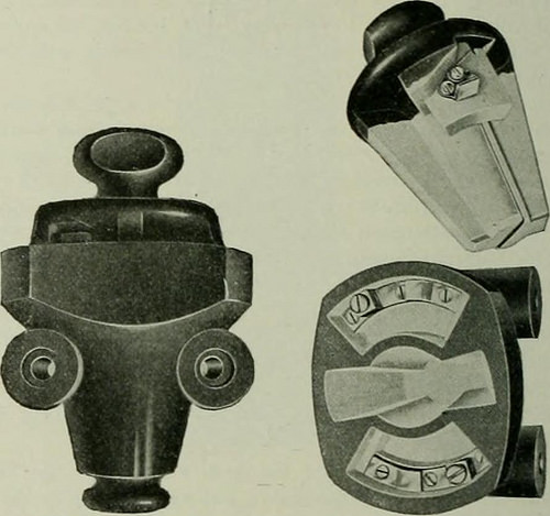
Image by Web Archive Book Pictures
Identifier: electricalworld43newy
Title: Electrical planet
Year: 1883 (1880s)
Authors:
Subjects: Electrical engineering
Publisher: [New York McGraw-Hill Pub. Co., and so forth.]
View Book Web page: Book Viewer
About This Book: Catalog Entry
View All Photos: All Images From Book
Click here to view book on-line to see this illustration in context in a browseable online version of this book.
Text Appearing Prior to Image:
te created and in-stalled the switchboard and circuits. An enhanced type of a transformer major reduce-out made toprotect the higher-tension side of transformers is becoming introduced bythe Westinghouse Electric & Manufacturing Business. It is madeentirely of porcelain, and its kind is such that it has high insulatingand arc-breaking qualities. The plug to which the fuse is attachedprojects between the terminals, the upper end of it rising nicely intothe top of the block and interposing an eflfective barrier, and thusmaking it not possible to preserve an arc. The fuse is eleven inchesin length, making a long break, and is so placed that the vapors ofa discharge are blown down and out of the device and away from theterminals. The line wire is carried straight to the best of the device and at-tached to it as to an ordinary insulator, which it as a result displaces. Toreach the terminal the wire need to be bent about the edge of theblock and is so supported in an angle in between the terminal post ami
Text Appearing Right after Image:
FIGS. I .AXD 2.—TR.VXSFORMER PRIM.RV Reduce-OUT. the porcelain case that it can not be loosened by any swaying of thew-ire in the wind. The pug enters from the bottom. When it is raised into location apartial turn draws the knife blades on the plug into the jaws onthe block, stopping the plug from dropping out or becoming blown out. All reside parts are protected from the weather by the projectingedges of the block, and b putting the terminals nicely above its lowersurface, with no apertures in the side or best. A bend in the fusewire brings it into plain view at all instances, and it is hence attainable toobserve its condition with no removing the plug, guarding againstany liability of opening the circuit when there is a existing upon theline. It is fastened to the cross arm or other assistance by two screws, pass-ing via porcelain tubes which form a portion of the block. Ithas a rated capacity of 2,500 volts, 30 amp., and is little, light, easyto set up and to re-fuse. Electric Heat in Theatres. Th
Note About Pictures
Please note that these images are extracted from scanned page pictures that could have been digitally enhanced for readability – coloration and appearance of these illustrations may not completely resemble the original work.
Image from page 542 of “Electrical news and engineering” (1891)
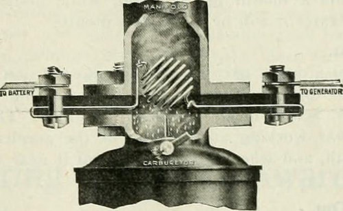
Image by Internet Archive Book Pictures
Identifier: electricalnewsen31donm
Title: Electrical news and engineering
Year: 1891 (1890s)
Authors:
Subjects: Electrical engineering
Publisher: Don Mills, Ont. [and so on.] Southam-Maclean Publications
View Book Page: Book Viewer
About This Book: Catalog Entry
View All Pictures: All Photos From Book
Click right here to view book on the web to see this illustration in context in a browseable online version of this book.
Text Appearing Before Image:
film upon the aluminumplate or plates in proper order. The device is capalble ofpassing a surge present of around 1000 amp. at doublenormal voltage when the arrester is functioning and onearrester ought to be employed for every single .500 kw. of feeder bus, rotaryconverter or motor-generator capacity to which the arresteris connected. Any voltage in excess of regular line voltageis discharged promptly through the arrester. The arrestersare mounted and securely held in asbestos board and wool-fibre-lined cypress boxes. Fuel Electrofier The Bukolt Manufacturing Firm have not too long ago placedon the marketplace a device for heating and vaporizing gasolinefuel iby indicates of electric heat ahead of it reaches the cylinder.It is claimed that this is achieved by indicates of a heatcoil of special material which produces heat at the leastresistance. The cut depicts the arrangement of the apparatuswhich includes a wire ball forming a screen via whichthe fuel need to pass. This ball is heated red-hot and trans-
Text Appearing Following Image:
types the liquid into gas ready for explosion under cylinderpressure. The heat coil is placed and connected in betweenthe carburetor and manifold on the charging line betweenthe generator and battery. Favor 12 Gallon Tank as Common The thought of standardizing on a 13 gallon tank forelectric homes, suggested in a current problem by Mr. S. H. Ex-cell of Vernon, B. C, has met with considerable favor. Hereare a couple of letters from electric merchants: Ottawa, Aug. 11.Editor Electrical News, Relating to H. S. Excells suggestion for 12 gallon watertank for household use. We are of the opinion that the 12gallon tank would be a lot more advantageous from an economi-cal point of view, and would give enough hot water for or-dinary each and every day use. It would also reduce the cost of in-stallation. Standardizing on the 12 gallon electrically heatedwater tank would be a step in the appropriate path.Yours truly, P. E. March and Toronto, Aug. three.Editor Electrical News:-— We are very in accord with Mr. Excells su
Note About Photos
Please note that these images are extracted from scanned page images that could have been digitally enhanced for readability – coloration and look of these illustrations could not completely resemble the original operate.
Image from page 400 of “The street railway assessment” (1891)
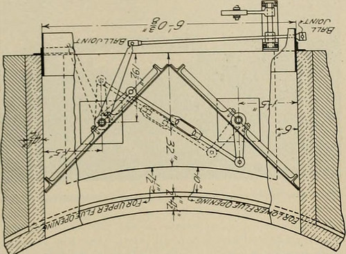
Image by Web Archive Book Pictures
Identifier: streetrailwayrev14amer
Title: The street railway evaluation
Year: 1891 (1890s)
Authors: American Street Railway Association Street Railway Accountants’ Association of America American Railway, Mechanical, and Electrical Association
Subjects: Street-railroads
Publisher: Chicago : Street Railway Review Pub. Co
View Book Page: Book Viewer
About This Book: Catalog Entry
View All Pictures: All Images From Book
Click here to view book on the internet to see this illustration in context in a browseable on-line version of this book.
Text Appearing Before Image:
s, the water willaverage as higher as the pumps, although for a portion of the yearthe water level will be way above the pumps, ft might even go ashigh as the elevation of the condenser outlets at the main station, JlNE 20, 1904.] STREET RAILWAY REIEW. 381 £or this was the flood elevation of Could 31, 1903, and in this casethe pumps will merely have to operate against the friction head dueto the length of pipe and passage via condensers in maintaining upa circulation. All pump discharge pipes have effortless bends as Hieyleave the pumps and at the tees on the main discharge. At thetop of each pipe near the tees are gate valves, which not only servethe purpose of shutting off each and every pump from the main line, butof holding the main supply pipe full or i)rimed for the duration of a completeshut-down of the pumping station, or the cutting out of any pumpor other valve for repairs. Midway up the pump chamlier is a platform with iron floor grat-ings, and the beams of this floor carry also the iuternicdlate shaft ■j.u/on
Text Appearing Soon after Image:
FIG. 1.>-DAMPKR MECHANISM iFLfE OIKNING Cxi ET.) bearings which take place near the intermediate couplings. All pumpchamber partition walls have doorways at this level which alloweasy access for the operators without having use of ladders. Just underthe main floor General Electric fle.vible shaft couplings are employed,supported by bearings each beneath and on the motor. At the topof every motor frame are thrust bearings, which arc automaticallyoiled from an oil pan on decrease frame by centrifugal force. Ihemotors are of the G. E. induction kind K, three-phase, 25 cycle,440 volts, and of two sizes, 125 ad 75 kw., each operating at .175r p m. The motor feet and footwear below them are provided withset screws to facilitate perfect alignment of motor and pump shafts,each vertically and horizontally. The compensators and switchesare situated at the west end of the station in a recess providedtherefor, below which is a wire connection chamber completely sep-arate from all water chambers. In thi-, the cable conduit
Note About Images
Please note that these images are extracted from scanned web page photos that could have been digitally enhanced for readability – coloration and appearance of these illustrations could not perfectly resemble the original function.