Verify out these electrical discharge grinding images:
Image from page 104 of “Electrical news and engineering” (1891)
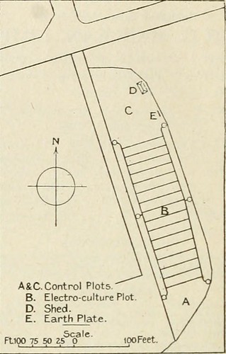
Image by World wide web Archive Book Pictures
Identifier: electricalnewsen27donm
Title: Electrical news and engineering
Year: 1891 (1890s)
Authors:
Subjects: Electrical engineering
Publisher: Don Mills, Ont. [and so forth.] Southam-Maclean Publications
Contributing Library: Engineering – University of Toronto
Digitizing Sponsor: University of Toronto
View Book Web page: Book Viewer
About This Book: Catalog Entry
View All Photos: All Pictures From Book
Click here to view book online to see this illustration in context in a browseable on the web version of this book.
Text Appearing Prior to Image:
se) King Ed-ward, 1.231 lb. (153 and 117 per cent, increase) Summit. 1.45111). (7.5 increase three.1 per cent, decrease). With regard to the Summits grown on Plot C, it shouldbe noted that the provide wire from the shed to the dischargewire was passed over this ground, at a height of 8 ft. Other vegetables had been grown, but, owing to late planting,no try was produced to get comparative result. Peas,beans, white turnips, swedes, and beet did properly carrots andonions have been very poor, both in top quality and quantity. Greens did nicely, and it was noticeable that these under electroculturewere not attacked Ijy caterpillar to the very same extent as thoseunder all-natural manage. No manure or fertilizer was utilized. The electrical equipment consisted of a ten in. coil, withmercury break-current interrupter and Lodge valves, housedin a wooden shed, 25 yards from the plot, and an earth plateclose to the plot. No. 30 s.w.g. galvanized steel wires wereused for the discharge, placed 15 ft. apart and hooked to 7/16
Text Appearing Right after Image:
A&C. Handle Plots B. Electro-culture Plot D. Shed. E. Earth Plate. ScaleFtK) 75 50 ZS one hundred Feet. Fg. 1—Plan of Ground Employed in. s.w.g. span wire attached to insulators, and the whole sup-ported by six poles. To each of the poles was fixed a wrought-iron bar, which enabled the discharge wire to be placed at anydistance from the ground among two ft. 6 in and six ft. six in.The apparatus was supplied with five amperes at 310 volts d.c,wliich would preserve a spark 54 in. long, when an earth wirewas placed that distance from any element of the discharge net-perform. At the commencement the discharge wire was placed asnear as possible to the ground, and, as the crop grew, raised Hours71- six- 5 ■ n L four- 3- J n If n r 1 ■ r nJ r u ^1 Fig. 2—Diagram showing hours per day discharge used to about six in. above the foliage. hen climate and other con-ditions allowed, the discharge was utilised from 6 a.m. to 8 a.m.and 6 p.m. to eight p.m. everyday, and during dull days in between mid-day and 2 p.m. In all the
Note About Photos
Please note that these photos are extracted from scanned web page photos that may have been digitally enhanced for readability – coloration and look of these illustrations could not perfectly resemble the original work.
Image from web page 373 of “Journal of electricity, energy, and gas” (1899)
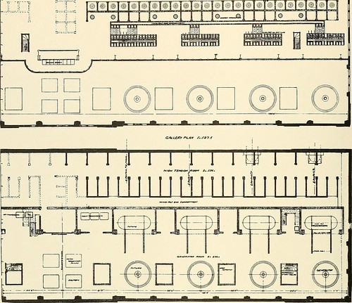
Image by Web Archive Book Images
Identifier: journalofele241251910paci
Title: Journal of electrical energy, power, and gas
Year: 1899 (1890s)
Authors: Pacific Coast Electric Transmission Association
Subjects: Electrical engineering Electricity Gas manufacture and works
Publisher: San Francisco : Technical Pub. Co.
Contributing Library: San Francisco Public Library
Digitizing Sponsor: California State Library Califa/LSTA Grant
View Book Page: Book Viewer
About This Book: Catalog Entry
View All Images: All Pictures From Book
Click here to view book on the web to see this illustration in context in a browseable on the internet version of this book.
Text Appearing Just before Image:
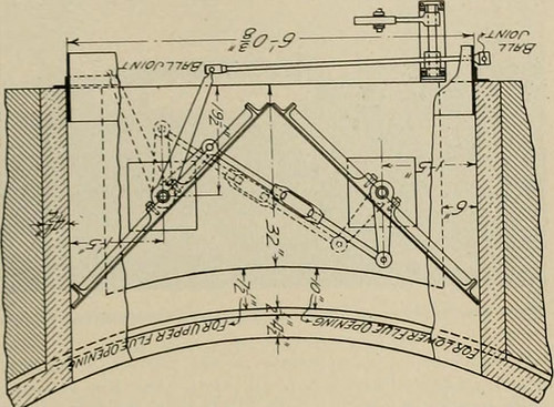
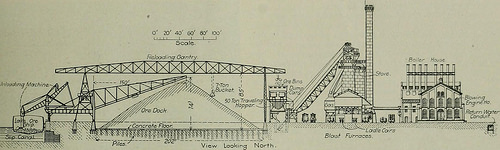
ween the energy-houseand the header. The pipe-lines, like the gate and butterfly valves,are 5 ft. inside diameter. They are sheet steel, weldedon the longitudinal seam, and vary in thickness from13/32 in. at the top to 43/64 in. at the reduce finish, was made in Philadelphia, the latter was riveted to-gether on the ground. The pipe-lines are supportedat intervals by concrete carried nicely down into thebedrock. The typical length is 700 ft. The Energy-House. The web site where the energy-home stands was orig-inally a steep mountainside, but was selected as itofifered a excellent strong rock foundation. A coffer-damwas erected, extending into the river to facilitate ex-cavation, which was carried down till all possibilityof any broken surface rock would be eliminated. Thebuilding is 183 ft. 4 in. lengthy and 71 ft. six in. wide. The foundations are of solid concrete under theheavy machinery, but the rear of the creating is sup- 324 ^.A A i! JOURNAL OF Electricity, Energy AND GAS [Vol. XXIV-No. 15 T I I ri: m
Text Appearing Soon after Image:
ra^ft^i. 00^ Fi.A/v ^t (T ported on concrete columns and arches, the whole con-stituting a piece of perform calculated to stand for alltime. The heavy concrete function is carried up to themain floor. The structure below the primary floor isdivided longitudinally by a heavy supporting wall andthe front also consists of such a wall. The penstocksand primary water-wheels are carried straight on the con-crete foundation, the draft-tubes passing down throughit and discharging under the front wall. The step-bearings and auxiliaries are carried on an arch floor,which is supported amongst the front and longitudinalwalls, and by transverse walls, although the generatorswhich are on the principal floor are also carried on archessimilarly supported. The creating above the major floor has a steelframe with reinforced concrete walls, which supporta steel truss reinforced concrete slab roof. It is dividedinto two longitudinal bays by a series of steel columns.A 50-ton, electrically-operated traveling crane forhandling
Note About Pictures
Please note that these pictures are extracted from scanned page photos that might have been digitally enhanced for readability – coloration and look of these illustrations could not completely resemble the original perform.
Image from web page 118 of “Electrical news and engineering” (1891)
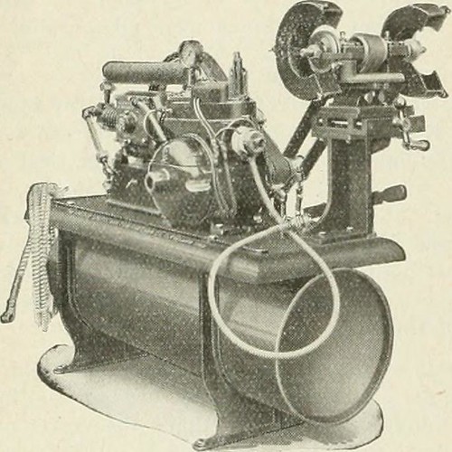
Image by Net Archive Book Images
Identifier: electricalnewsen27donm
Title: Electrical news and engineering
Year: 1891 (1890s)
Authors:
Subjects: Electrical engineering
Publisher: Don Mills, Ont. [etc.] Southam-Maclean Publications
Contributing Library: Engineering – University of Toronto
Digitizing Sponsor: University of Toronto
View Book Page: Book Viewer
About This Book: Catalog Entry
View All Images: All Pictures From Book
Click here to view book on-line to see this illustration in context in a browseable online version of this book.
Text Appearing Ahead of Image:
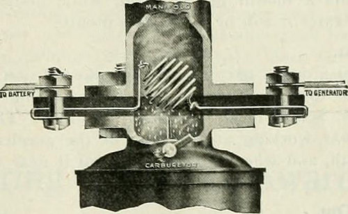
th plug, all mounted on a metal base to forma compact unit, which needs but 48 x 20 inches floor space.T!ie lieight more than all is 40 inches. The air compressor is theair-cooled, two-stage type. The low stress cylinder is three x3 inches in size and the higher stress cylinder is IJ^ x 3inches. The operating stress is 300 pounds per square inch,and the capacity of the compressor is four cubic feet per minute.The compressor operates at 250 to 300 r.p.ni. It is providedwith an intake silencer, which muffles tlie intake noise andtends to force air into the intake valve. When the air in themain tank is raised to the appropriate stress the automaticswitch stops the motor and operates the automatic pressurerelease, which opens beginning tank to the atmosphere. Whenthe automatic switch again begins the motor it also closes thepressure release, and the compressor starts pumping againstno pressure. It always begins with no strain. When the airin the starting tank attains a pressure slightly in excess of
Text Appearing Soon after Image:
that in the primary tank (requiring about ten seconds) it opensthe check valve and charges this tank till the appropriate pres-sure is reached, when the operations are repeated. A trap isprovided in the starting tank, which extracts any moisture oroil that could be discharged from the compressor, assuringpure, dry air, cost-free from oil. The buffing and grinding head issuitable for wheels of 8-inch diameter. The outfit is equippedwith a a single horse-power Robbins & Myers motor, which per-mits the compressor and buffing head to operate at the sametime. Outfits with no this buffing head are equipped witli aone-lialf horse-energy R & M motor. New Flood-Lighting Projector for Regular Mazda C LampsA new flood-lighting projector, made for use of 300to 1,000-watt common Mazda C lainps, has been placedon the industry by the George Cutter Organization, South Bend,Ind. It is named the Standard Flood-Lighting Projector.The new unit has the identical common construction features asthe Cutter Universal project
Note About Images
Please note that these images are extracted from scanned page photos that could have been digitally enhanced for readability – coloration and look of these illustrations may possibly not perfectly resemble the original operate.
")


")