Some cool electrical discharge grinding images:
Image from page 542 of “Electrical news and engineering” (1891)
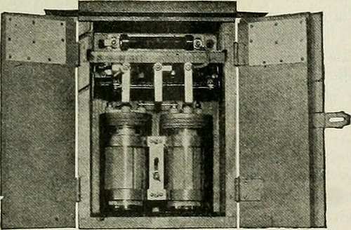
Image by Web Archive Book Pictures
Identifier: electricalnewsen31donm
Title: Electrical news and engineering
Year: 1891 (1890s)
Authors:
Subjects: Electrical engineering
Publisher: Don Mills, Ont. [etc.] Southam-Maclean Publications
Contributing Library: Engineering – University of Toronto
Digitizing Sponsor: University of Toronto
View Book Page: Book Viewer
About This Book: Catalog Entry
View All Pictures: All Images From Book
Click right here to view book on-line to see this illustration in context in a browseable on the internet version of this book.
Text Appearing Prior to Image:
the energy losses of distribution by maintaining down a leakagefrom the conductor to the insulator pin. The clamps aremade of malleable iron, galvanized by the hot dipping pro-cess. Each halves are alike and interchangeable. The manu-facturers claim that these clamps will not break the glass,as there is but 1 bolt and the covering of the conductor re-ceives the stress that may possibly outcome from unequal expansion. Direct-Current Lightning ArresterA direct existing electrolytic lightning arrester, for volt-age applications up to three,800 volts has been lately devel-oped by the Westinghouse Electric & Manufacturing Com-pany. The device contains one to twelve cells and is de-signed for car or station use on railway, energy and lightingcircuits. The building embodies two aluminum platesimmersed in a suitable inorganic electrolyte and supportedfrom a porcelain cover clamped by a zinc ring to a glass jar
Text Appearing After Image:
with a gasket placed bctvvcLii the porcelain cover and theglass jar. Hollow concentric cylinders produced from sheet aluminumform the plates, the outer cylinder or plate getting punched andupset at frequent intervals in order to allow free of charge circulation of the electrolyte inside the cell. Balancing resistors areused with arresters of a lot more than one particular cell. The arrestersare floated between the line and ground, so that a leakagecurrent of only a handful of milliamperes passes continually. Thisleakage current serves to preserve the film upon the aluminumplate or plates in proper order. The device is capalble ofpassing a surge present of roughly 1000 amp. at doublenormal voltage when the arrester is functioning and onearrester must be used for each .500 kw. of feeder bus, rotaryconverter or motor-generator capacity to which the arresteris connected. Any voltage in excess of normal line voltageis discharged promptly by means of the arrester. The arrestersare mounted and securely held in asbestos board and w
Note About Images
Please note that these images are extracted from scanned page pictures that may have been digitally enhanced for readability – coloration and look of these illustrations may possibly not perfectly resemble the original perform.
Image from page 33 of “Electrical planet” (1883)
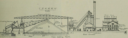
Image by Web Archive Book Images
Identifier: electricalworld43newy
Title: Electrical planet
Year: 1883 (1880s)
Authors:
Subjects: Electrical engineering
Publisher: [New York McGraw-Hill Pub. Co., etc.]
Contributing Library: Engineering – University of Toronto
Digitizing Sponsor: University of Toronto
View Book Page: Book Viewer
About This Book: Catalog Entry
View All Photos: All Images From Book
Click here to view book online to see this illustration in context in a browseable on the web version of this book.
Text Appearing Ahead of Image:
ft. in length, it ha- boonanchored at the center of each and every side of the boiler home. A double 20 40 60 80 100 vcys it to any essential point. This is in the nature of a travelingcrane, and its character can be readily understood from Fig. ten. Theashes are discharged in the basement into a pocket of a capacity of28 cu. ft., which travels on an overhead trolley. From this the ashesare dumped into a skip, which elevates them to the ash bin, fromwhich they iie automatically discharged into automobiles as preferred. .All ofthe machinery is operated by direct-existing motors. The coal-hand-ling and ash-conveying systems had been de>igned by Heyl and Patter-son, of Pittsburg. Boiler residence No. i in its common attributes is comparable to the onealready described. This includes 16 Cahall boilers, which are pro-vided with grates and gas fired. Coal is utilized whenever the blastfurnace gas is of an inferior quality. Boiler home No. three, which is.south of the pumping station, is 65 . 184 ft. in size. This will con-
Text Appearing Right after Image:
Unl^adtnq Machine-^ ^~^ v s^~nJ: Fig. 5.—Section By means of Ore Dock and Blast Furnaces. bend is provided in each line, connecting a battery with the mainheader to take care of expansion. A really lengthy elbow is provided ateach boiler, which, by closing two valves located in between the headerand the former, can be completely removed to permit the removal oftubes. A monitor in two halves of a bigger diameter than the boileris bolted to the roof more than every. This can be entirely removed forrepairs of what ever nature, and also serves as a ventilator. Allsteam valves 12 in. long or bigger are by-passed. Drips under oper-ating situations are exposed, and eight-in. cast-iron pipe is utilized forblow-offs in the ground -leading to the sewers. Compressed air is tain 32 Cahall boilers gas fired, and will furnish steam to several en-gines in the Bessemer rail mill. As already stated, each and every pair of blast furnaces will have its ownpower home, containing an gear of gas engines for drivingblower engi
Note About Pictures
Please note that these photos are extracted from scanned web page photos that might have been digitally enhanced for readability – coloration and appearance of these illustrations may not perfectly resemble the original function.
Image from web page 377 of “Journal of electricity, power, and gas” (1899)
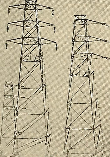
Image by Web Archive Book Pictures
Identifier: journalofele323271914paci
Title: Journal of electrical energy, power, and gas
Year: 1899 (1890s)
Authors: Pacific Coast Electric Transmission Association
Subjects: Electrical engineering Electrical energy Gas manufacture and performs
Publisher: San Francisco : Technical Pub. Co.
Contributing Library: San Francisco Public Library
Digitizing Sponsor: California State Library Califa/LSTA Grant
View Book Page: Book Viewer
About This Book: Catalog Entry
View All Pictures: All Photos From Book
Click right here to view book online to see this illustration in context in a browseable on-line version of this book.
Text Appearing Before Image:
Text Appearing Right after Image:
_■. w.-.rti2najii>fe^ j«,£5<aitaMBMH Towers at Tiny Falls Showing Rock Anchorages. beneath the supervision of an inspector employed by thepurchaser, who kept a close supervision of the work-manship and produced frequent tests on samples selectedby him. A single of the 50 ft. towers was erected at thecontractors operates for inspection and to prove the cor-rectness of the style was subjected to all the stressesprovided for in the specifications. Ground Wires. Two ground wires are supplied and they are at-tached both mechanically and electrically to the topof the towers. Each ground wire consists of a ^ in.diam., seven strand Siemens-Martin steel cable hav-ing an ultimate strength of about 9000 lb. and anelastic limit of 5500 lb. These ground wires are pro-vided to afford protection from lightning discharges.No matter whether they do or do not furnish this protection theauthor is unable to state, from his personal encounter,but believes that they do. A lot of engineers claim thatowing to the ground wires
Note About Images
Please note that these images are extracted from scanned web page pictures that could have been digitally enhanced for readability – coloration and appearance of these illustrations may possibly not completely resemble the original function.