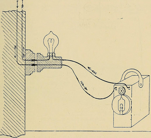
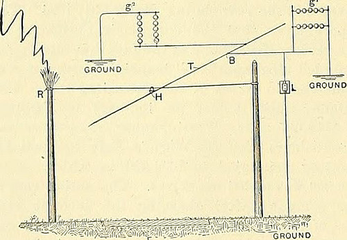
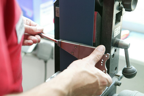
Check out these prototype manufacturing organization photos:
“Joaninha” (Renault four CV)
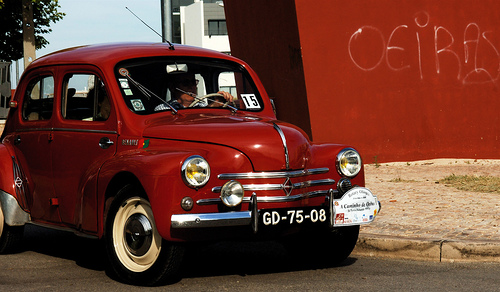
Image by pedrosimoes7
Oeiras, Portugal
in Wikipedia
The Renault 4CV is an economy vehicle created by the French manufacturer Renault from August 1947 to July 1961. As the first French automobile to sell over a million units, the 4CV was in the end superseded by the Renault Dauphine.
The 4CV was a four-door sedan of monocoque construction,[1] three.6 meters in length with rear suicide doors[three] and using Renault’s Ventoux engine in a rear-engine, rear-wheel drive layout.
The car’s name, 4CV, translates from the French for 4 cheveaux or 4 horse, especially four taxable horsepower.
To celebrate the fiftieth anniversary of the debut of the 4CV, in 1996 Renault presented a totally roadworthy concept car, the Renault Fiftie, with styling that recalled the 4CV, only in a two-door, mid-engine design and style.
Conception and history
The 4CV was originally conceived and designed covertly by Renault engineers throughout the German occupation of France in the course of Planet War II, when the manufacturer was under strict orders to design and create only industrial and military vehicles. A design group led by Fernand Picard, Charles-Edmond Serre and Jean-Auguste Riolfo envisioned a tiny, economical automobile appropriate for the economically tough years which would inevitably stick to the war.
The first prototype was completed in 1942 and two a lot more prototypes had been developed in the following 3 years. Pierre Lefaucheux tested the four CV prototype at Renault’s Herqueville estate.[four] The 4CV was ultimately presented to the public and media at the 1946 Paris Motor Show. The cars went on sale a year later.
In 1940 Louis Renault had directed his engineering team to "make him a car like the Germans". And until the arrangement was simplified in 1954, the 4CV featured a ‘dummy’ grill comprising six thin horizontal chrome strips, intended to distract focus from the similarity of the car’s all round architecture to that of the German Volkswagen,[1] whilst recalling the modern day designs of the fashionable front engined passenger vehicles produced in Detroit throughout the earlier 1940s.
An essential portion of the 4CV’s achievement, owes to the new methodologies employed in its manufacture, pioneered by Pierre Bézier. Bézier had begun his 42 year tenure at Renault as a Tool Setter, moving up to Tool Designer and then becoming head of the Tool Style Office. As Director of Production Engineering in 1949, he developed the transfer lines (or transfer machines) making most of the mechanical components for the 4CV.[5] The transfer machines were higher-functionality function tools designed to machine engine blocks. Even though imprisoned for the duration of WWII, Bézier created and enhanced on the automatic machine principle, introduced before the war by GM (Basic Motors). The new transfer station with several workstations and electromagnetic heads (antecedants to robots), enabled different operations on a single component to be consecutively performed by transferring the part from one particular station to another.
On the 4CV’s launch, it was nicknamed "La motte de beurre"(the lump of butter) — due to the combination of its shape and the truth that early deliveries all utilized surplus paint from the German Army autos of Rommel’s Afrika-Corps, in a sand-yellow colour.[1] The 4CV was initially powered by a 760cc rear mounted four-cylinder engine coupled to a three-speed manual transmission. [7] In 1950 the 760cc unit was replaced by a 747cc version [7] of the "Ventoux" engine creating 17 hp (13 kW).
In spite of an initial period of uncertainty and poor sales due to the ravaged state of the French economy, the 4CV had sold 37,000 units by mid-1949 and was the most well-known vehicle in France. The auto remained in production for much more than a decade afterwards. Claimed power output elevated subsequently to 21 hp (16 kW) as increased fuel octanes allowed for larger compression ratios, which along with the comparatively low weight of the vehicle (620 kg) enabled the companies to report an – 90 km/h (56 mph) time of 38 seconds and a prime speed barely beneath one hundred km/h (62 mph).[1] The engine was notable also for its elasticity, the second and prime gear both becoming usable for speeds between five km/h (three mph) and 100 km/h (62 mph): the absence of synchromesh on first gear would presumably have discouraged use of the bottom gear except when beginning from rest.
The rear mounting of the engine meant that the steering could be highly geared even though remaining reasonably light: in the early vehicles only 2¼ turns had been required from lock to lock.[1] The unusually direct steering no doubt delighted some keen drivers, but road tests of the time nonetheless included warnings to take great care with the car’s handling on wet roads.[1] In due course the makers switched from 1 intense to the other, and on later vehicles 4½ turns had been needed to turn the steering wheel from lock to lock.
The 4CV’s direct replacement was the Dauphine, launched in 1956, but the 4CV in fact remained in production until 1961. The 4CV was replaced by the Renault 4 which utilised the identical engine as the 4CV and sold for a similar cost.
Although most of the vehicles had been assembled at Renault’s Île Seguin plant located on an island in the river opposite Billancourt, the 4CV was also assembled in seven other countries, becoming Australia, Belgium, England, Ireland, Japan (where the Hino assembled examples gained a reputation for superior quality[1]), Spain and South Africa.[1] 1,105,543 vehicles were made the 4CV became the very first French vehicle to sell over a million.
The 4CV was easily modified and was utilized extensively as a racing auto. The 1st collaboration in between the Alpine business and Renault was the Alpine A-106 which was based on the 4CV. The partnership which would go on to win the Planet Rally Championship with the legendary Alpine A-110 in later years,
Renault four CV
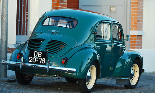
Image by pedrosimoes7
Belem, Lisbon, Portugal
in Wikipedia
The Renault 4CV is an economy vehicle developed by the French manufacturer Renault from August 1947 to July 1961. As the very first French automobile to sell over a million units, the 4CV was eventually superseded by the Renault Dauphine.
The 4CV was a four-door sedan of monocoque construction,[1] 3.6 meters in length with rear suicide doors[3] and using Renault’s Ventoux engine in a rear-engine, rear-wheel drive layout.
The car’s name, 4CV, translates from the French for 4 cheveaux or 4 horse, particularly 4 taxable horsepower.
To celebrate the fiftieth anniversary of the debut of the 4CV, in 1996 Renault presented a totally roadworthy idea automobile, the Renault Fiftie, with styling that recalled the 4CV, only in a two-door, mid-engine style.
Conception and history
The 4CV was initially conceived and created covertly by Renault engineers for the duration of the German occupation of France for the duration of Planet War II, when the manufacturer was beneath strict orders to design and style and produce only commercial and military cars. A design and style team led by Fernand Picard, Charles-Edmond Serre and Jean-Auguste Riolfo envisioned a little, economical car appropriate for the economically difficult years which would inevitably adhere to the war.
The initial prototype was completed in 1942 and two far more prototypes had been created in the following three years. Pierre Lefaucheux tested the four CV prototype at Renault’s Herqueville estate.[4] The 4CV was ultimately presented to the public and media at the 1946 Paris Motor Show. The automobiles went on sale a year later.
In 1940 Louis Renault had directed his engineering team to "make him a vehicle like the Germans". And until the arrangement was simplified in 1954, the 4CV featured a ‘dummy’ grill comprising six thin horizontal chrome strips, intended to distract interest from the similarity of the car’s overall architecture to that of the German Volkswagen,[1] whilst recalling the modern designs of the fashionable front engined passenger vehicles developed in Detroit in the course of the earlier 1940s.
An important component of the 4CV’s accomplishment, owes to the new methodologies utilized in its manufacture, pioneered by Pierre Bézier. Bézier had begun his 42 year tenure at Renault as a Tool Setter, moving up to Tool Designer and then becoming head of the Tool Design and style Office. As Director of Production Engineering in 1949, he designed the transfer lines (or transfer machines) creating most of the mechanical components for the 4CV.[5] The transfer machines had been high-efficiency function tools developed to machine engine blocks. Although imprisoned throughout WWII, Bézier developed and enhanced on the automatic machine principle, introduced ahead of the war by GM (Common Motors). The new transfer station with numerous workstations and electromagnetic heads (antecedants to robots), enabled various operations on a single element to be consecutively performed by transferring the part from one particular station to one more.
On the 4CV’s launch, it was nicknamed "La motte de beurre"(the lump of butter) — due to the mixture of its shape and the reality that early deliveries all utilised surplus paint from the German Army automobiles of Rommel’s Afrika-Corps, in a sand-yellow color.[1] The 4CV was initially powered by a 760cc rear mounted 4-cylinder engine coupled to a three-speed manual transmission. [7] In 1950 the 760cc unit was replaced by a 747cc version [7] of the "Ventoux" engine creating 17 hp (13 kW).
Despite an initial period of uncertainty and poor sales due to the ravaged state of the French economy, the 4CV had sold 37,000 units by mid-1949 and was the most well-liked car in France. The auto remained in production for more than a decade afterwards. Claimed energy output improved subsequently to 21 hp (16 kW) as enhanced fuel octanes allowed for higher compression ratios, which along with the comparatively low weight of the auto (620 kg) enabled the producers to report an – 90 km/h (56 mph) time of 38 seconds and a prime speed barely under 100 km/h (62 mph).[1] The engine was notable also for its elasticity, the second and best gear each being usable for speeds in between 5 km/h (three mph) and 100 km/h (62 mph): the absence of synchromesh on first gear would presumably have discouraged use of the bottom gear except when starting from rest.
The rear mounting of the engine meant that the steering could be very geared while remaining comparatively light: in the early automobiles only 2¼ turns have been needed from lock to lock.[1] The unusually direct steering no doubt delighted some keen drivers, but road tests of the time nonetheless integrated warnings to take wonderful care with the car’s handling on wet roads.[1] In due course the makers switched from 1 intense to the other, and on later vehicles 4½ turns were necessary to turn the steering wheel from lock to lock.
The 4CV’s direct replacement was the Dauphine, launched in 1956, but the 4CV in truth remained in production till 1961. The 4CV was replaced by the Renault 4 which utilized the identical engine as the 4CV and sold for a related value.
Although most of the cars were assembled at Renault’s Île Seguin plant positioned on an island in the river opposite Billancourt, the 4CV was also assembled in seven other countries, becoming Australia, Belgium, England, Ireland, Japan (where the Hino assembled examples gained a reputation for superior good quality[1]), Spain and South Africa.[1] 1,105,543 cars have been created the 4CV became the first French automobile to sell over a million.
The 4CV was effortlessly modified and was employed extensively as a racing vehicle. The very first collaboration amongst the Alpine organization and Renault was the Alpine A-106 which was primarily based on the 4CV. The partnership which would go on to win the Globe Rally Championship with the legendary Alpine A-110 in later years,
")


")